Service Guide N5230-90024 7-21
PNA Series Microwave Network Analyzers Repair and Replacement Procedures
N5230C Removing and Replacing the A15 CPU Board
Replacement Procedure
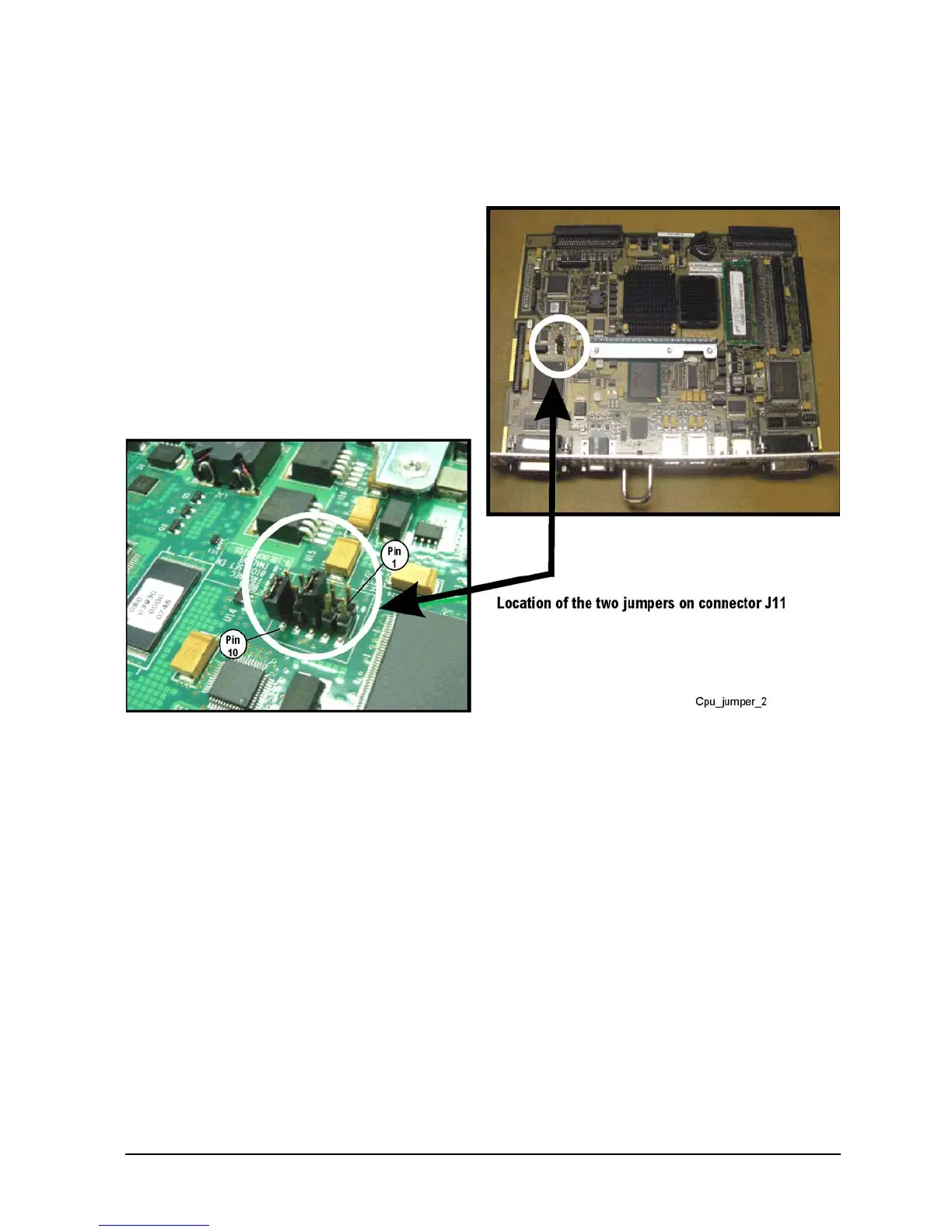
NOTE: If not already done, install a jumper between pins 9 and 10 on connector J11. See the following
illustration for the J11 pin configuration. There should already be a jumper between pins 5 and 6.
1. Reverse the order of the removal procedure.
2. If a new Certificate of Authenticity (license) label is supplied with your new A15 CPU board, adhere it to
the outer cover in the location specified in Figure 7-1 on page 7-7.
3. Perform the post-repair adjustments, verifications, and performance tests that pertain to this removal
procedure. Refer to Table 7-2 on page 7-54.

 Loading...


