3-24 Service Guide N5230-90024
Tests and Adjustments PNA Series Microwave Network Analyzers
System Verification N5230C
4. In the Calibration Kit box, select the calibration kit that is being used by clicking on it. The corresponding
verification kit to use is selected for you and displayed in the Verification Kit box. Refer to Figure 3-10.
5. Under Printer Output, click one of the following options. Refer to Figure 3-10.
• None: No printout of results.
• Tabu la r Da ta : Prints the verification data in tabular form which includes measured data and
uncertainty limits. For an example, refer to Figure 3-13 on page 3-26.
• Measurement Plots: Prints the verification data in graphical form. The graphical form includes the
measured data trace, factory supplied data trace, and uncertainty limits. For an example, refer to
Figure 3-14 on page 3-27.
• Both: Prints the verification data in both formats.
NOTE For printed output, it is assumed that the printer has been tested and the Windows 2000
driver is installed for the printer that is being used. The system verification test prints to the
printer that has been designated as the default printer. (On the Windows Desktop display,
click on My Computer, Control Panel, and then Printers to verify the printer setup.)
6. Click Run.
7. Follow the instructions on the analyzer for performing a full 2-port calibration.
8. After completion of the full 2-port calibration, follow the instructions on the analyzer for performing the
system verification.
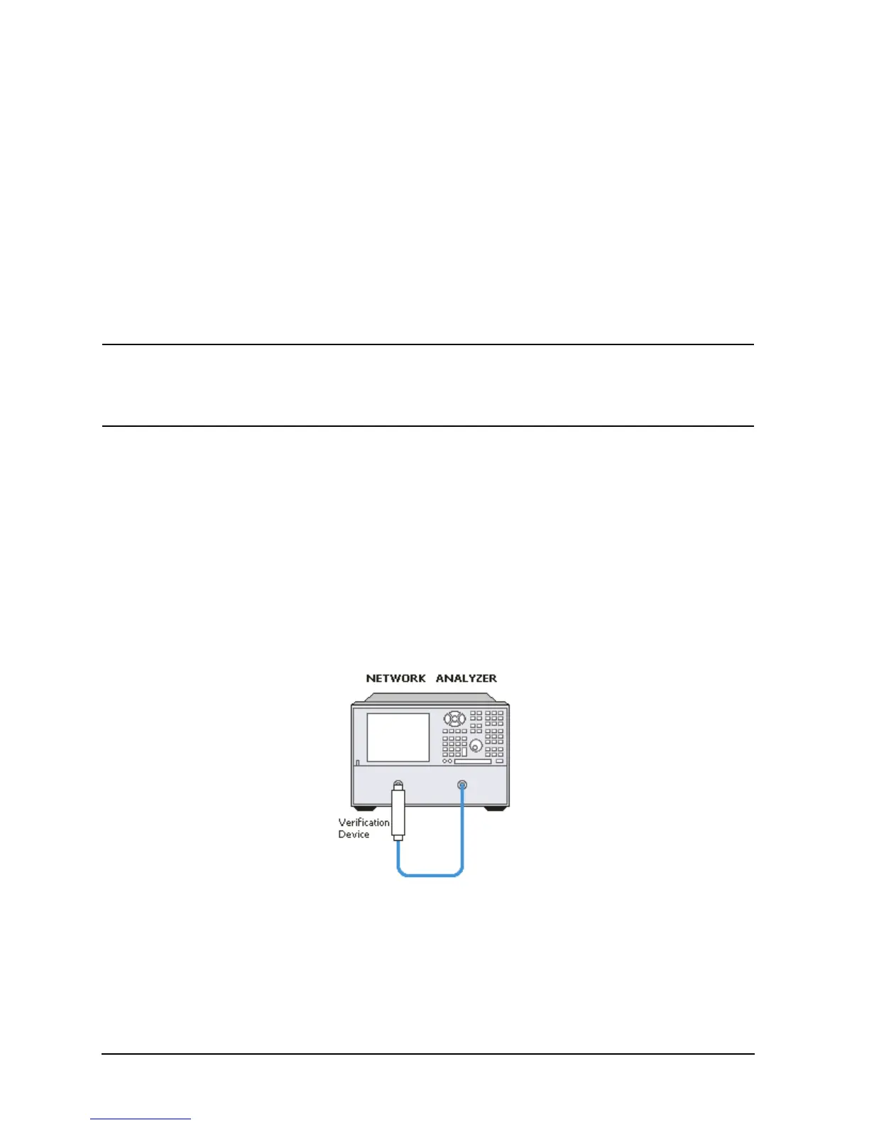
For the system verification, insert the devices as shown in Figure 3-11.
Figure 3-11 System Verification Device Connections