4-22 Service Guide N5230-90024
Troubleshooting PNA Series Microwave Network Analyzers
Rear Panel Troubleshooting N5230C
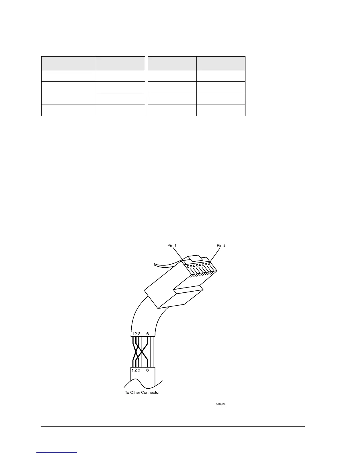
2. Cut the wires going to pins 1, 2, 3, and 6. Strip away a small amount of insulation from each of the eight
cut ends.
a. Connect the wire from pin 1 on one end of the cable to the wire from pin 3 on the other end of the
cable.
b. Connect the wire from pin 3 on one end of the cable to the wire from pin 1 on the other end of the
cable.
c. Connect the wire from pin 2 on one end of the cable to the wire from pin 6 on the
other end of the cable.
d. Connect the wire from pin 6 on one end of the cable to the wire from pin 2 on the
other end of the cable.
3. Insulate all exposed wires so that they cannot short together.
4. Label this as a crossover cable so that it cannot be confused with a standard cable.
Figure 4-5 Construction of a Crossover Cable
Table 4-3 LAN Pin Definitions and Wire Color Codes
Pin Number Color Pin Number Color
1 (transmit +) White/orange 5 White/blue
2 (transmit ) Orange 6 (receive )Green
3 (receive +) White/green 7 White/brown
4Blue8Brown