17
Connection
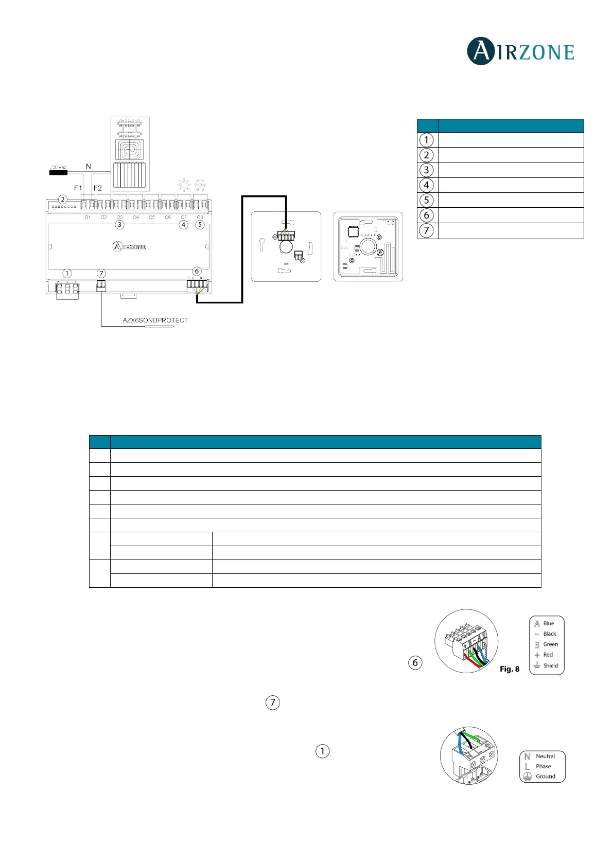
The Control Module of Radiant Elements is a device which connects to the Airzone connection bus of the main board (Fig. 7).
Control relay specs: I
max
= 10 A at 110/230 Vac, voltage-free.
Note that to control elements with a greater power, it is recommended to use contactors in accordance with the power
required. Remember to connect the neutral connector directly from the circuit to the element to be controlled.
Operation of the relays:
Note: If the zones 7 and 8 are not associated, the O7 and O8 control realys mantain the Mode
logic as in the installation without CCP. Once zones 7 and 8 have been associated, must do a
system reset if it is required to revert the configuration.
It has a 5-pin terminal to connect it to the Airzone connection bus of the main board .
Attach the wires with the terminal screws following the color code (Fig. 8).
Connect the temperature probe to the digital input of the Control Module of Radiant
Elements (AZRA6OUTPUT8Z). The other end of the temperature probe should be
connected to the manifold pipe.
Powe supply is connected to the module through a 3-pin terminal . Attach the wires with
the terminal screws following the color code (Fig. 9).
Once powered, The Control Module of Radiant Elements performs a sequential opening-
closing of all relay outputs. This operation is repeated once a week to ensure the correct
operation of the valves.
Radiant element demand - Zone 1
Radiant element demand - Zone 2
Radiant element demand - Zone 3
Radiant element demand - Zone 4
Radiant element demand - Zone 5
Radiant element demand - Zone 6
O7
Heating demand / Radiant element demand - Zone 7
O8
Cooling demand / Radiant element demand - Zone 8
Cooling demand / Zone relay
Cooling demand / Zone relay


 To Next Page