19
It has a 5-pin terminal to connect it to the Airzone connection bus of the main board . Attach
the wires with the terminal screws following the color code (Fig. 12).
Powe supply is connected to the module through a 3-pin terminal . Attach the wires with
the terminal screws following the color code (Fig. 13).
Important: According to the current local and national regulations, it is mandatory to add a
switch (or other element to disconnect the system) to the external supply wiring so that a
constant separation between poles is guaranteed. The system will restart automatically if the
supply is eventually turned off.
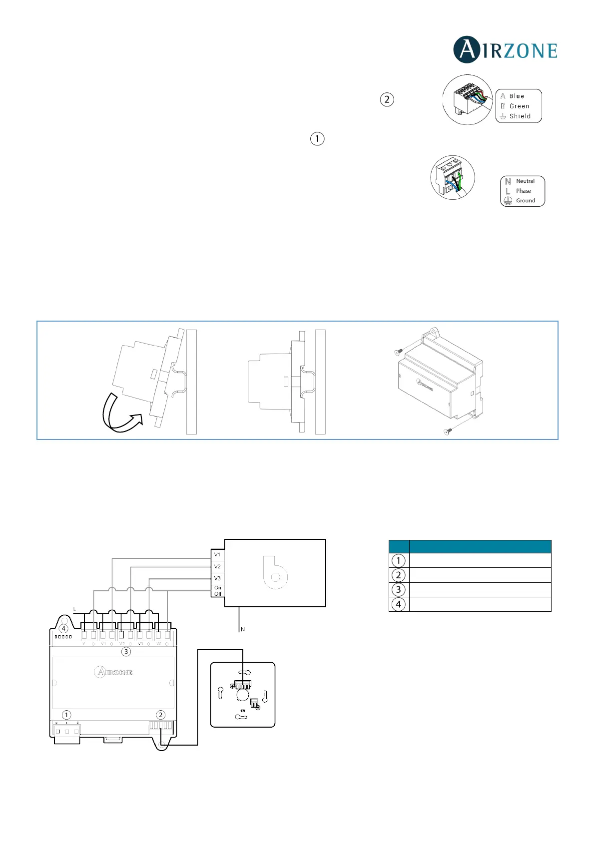
Assembly
The Airzone Control Module of Radiant Elements is mounted on DIN rail (Fig. 10). It is externally powered at 110/230 Vac.
Location and installation of the module must comply the current electronic rules.
Fig. 10
Note: To take the module away, pull the reed down to release it.
Connection
The Airzone 3 speeds/stages dehumidifier control module is a device which connects to the Airzone connection bus of the
main board (Fig. 11).
Control relay specs: I
max
= 10 A at 110/230 Vac, voltage-free.
Dehumidifier control relays
 Loading...