20
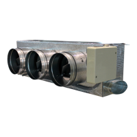
Note that to control elements with a greater power, it is recommended to use contactors in
accordance with the power required. Remember to connect the neutral connector directly from
the circuit to the element to be controlled.
Operation of the relays:
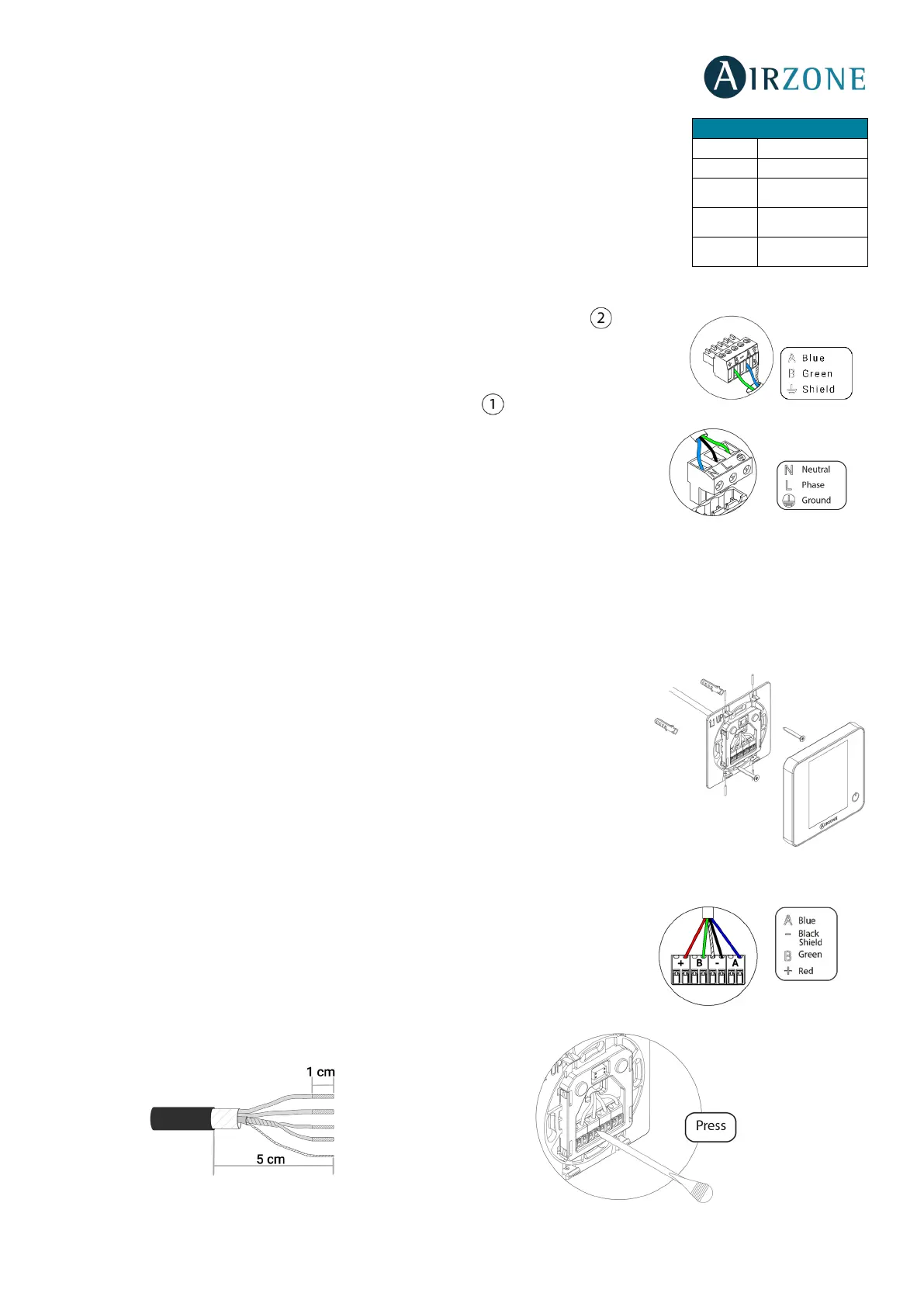
It has a 5-pin terminal to connect it to the Airzone connection bus of the main board . Attach
the wires with the terminal screws following the color code (Fig. 12).
Powe supply is connected to the module through a 3-pin terminal . Attach the wires with
the terminal screws following the color code (Fig. 13).
Important: According to the current local and national regulations, it is mandatory to add a
switch (or other element to disconnect the system) to the external supply wiring so that a
constant separation between poles is guaranteed. The system will restart automatically if the
supply is eventually turned off.
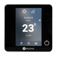
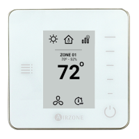
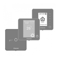
AIRZONE WIRED THERMOSTATS (AZRA6BLUEFACEC / AZRA6THINKC / AZRA6LITEC)
Assembly
Wired thermostats are mounted on the wall through a support. It is recommended not to locate it more than 40 meters away
from the main control board. To fix it to the wall, follow these steps (Fig. 14):
• Separate the back part of the thermostat from the wall support and make all the
connections.
• Fix the back part of the thermostat to the wall.
• Place the display on the support once it is fixed.
• Place the anti-theft rods for additional support (optional).
Connection
The Airzone thermostats are connected to the Airzone connection bus of the main board.
Attach the wires with the terminal screws following the color code (Fig. 15).
Important: Use a suitable screwdriver to press in the locking tabs (Fig. 16).
2
Speed 2
3
Speed 3
On / Off