34
Connection
It connects to the domotic bus of the main control board (Fig. 47).
Fig. 47
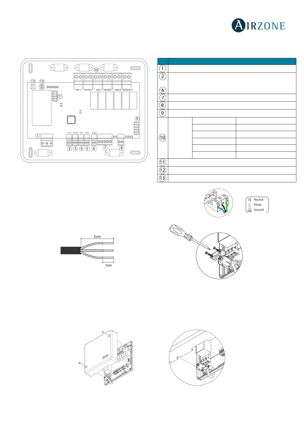
Power supply connector
This connector powers the main control board and all the elements connected to it.
Externally powered at 110/230 Vac. It is connected through a 3-pin terminal. Attach
the wires with the terminal screws following the color code (Fig. 48).
For added security, secure the wires using the turret (Fig. 49).
Fig. 49
Important: According to the current local and national regulations, it is mandatory to add a switch (or other element to
disconnect the system) to the external supply wiring so that a constant separation between poles is guaranteed. The system
will restart automatically if the supply is eventually turned off.
Remember: Once all the connections are made, make sure you replace the cover properly (Fig. 50).
…
Digital inputs
Control
relays