HM135 Service Manual
Preliminary version Page 10 of 13
3 ADJUSTMENTS
3.1 General
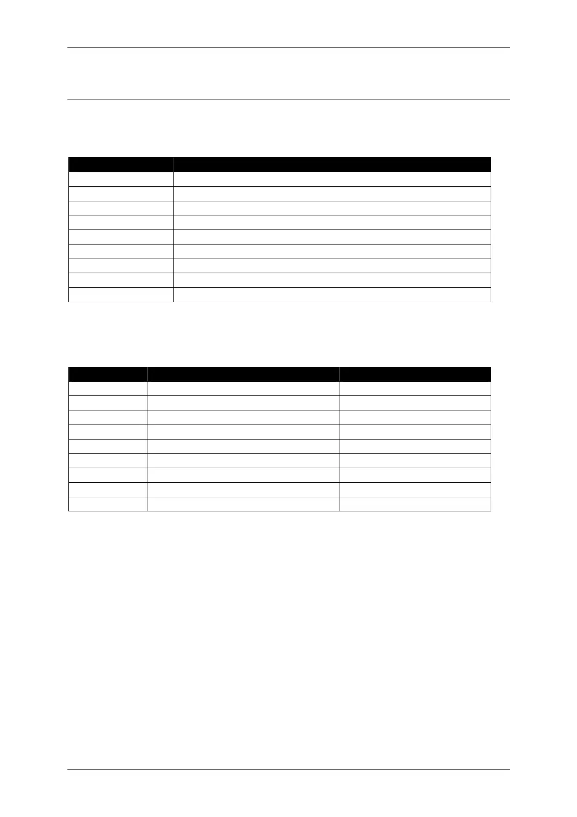
Adjustment trimmer potentiometer/capacitors in the HM135 main unit:
Ref. Designator Used for…
RP1
Squelch Level Adj.
RP2
Frequency Adj.
RP3
Deviation Balance ( Reference Oscillator Modulation Level)
RP4
Maximum Deviation Adj.
RP5
Transmitter Driver Bias Adj.
RP6
Transmitter Power Amplifier Bias Adj.
RP7
Transmitter Maximum Power Adj.
CV1
Receiver VCO Adj.
CV2
Transmitter VCO Adj.
3.2 Initial Settings
DO NOT CONNECT THE RADIO TO THE POWER SUPPLY BEFORE AND DURING INITIAL SETTINGS
OF CONTROLS.
1) Connect an ohmmeter between the wiper of RP3 and Ground. Turn RP3 in CCW direction until readings of the ohmmeter
are within 100 to 500 Ohm
2) Connect an ohmmeter between the wiper of RP5 and Ground. Turn RP5 in CCW direction until readings of the ohmmeter
are within 100 to 300 Ohm
3) Connect an ohmmeter between the wiper of RP6 and Ground. Turn RP6 in CCW direction until readings of the ohmmeter
are within 100 to 300 Ohm
4) Connect an ohmmeter between the wiper of RP7 and Ground. Turn RP7 in CCW direction until readings of the ohmmeter
are within 200 to 500 Ohm
3.3 Applying power for the first time.
RF Power amplifier and AF Power Amplifier of the radio are connected to the power supply before the
internal ON/OFF Switch, i.e. supply voltage is present even if the ON/OFF Switch is in OFF position. It
is strongly recommended to disconnect the radio from the plus of the power supply if full switching
OFF is needed.
Keep the minus of the Power Supply Unit connected to the GROUND.
Use pre-programmed and checked Front Panel.
Control Function Initial Settings
RP1
Squelch Level Adj. Center
RP2
Frequency Adj. Center
RP3
Deviation Balance Minimum (CCW), see note1.
RP4
Maximum Deviation Adj. Center
RP5
Transmitter Driver Bias Adj. Minimum, see note 2
RP6
Transmitter Power Amplifier Bias Adj. Minimum, see note 3
RP7
Transmitter Maximum Power Adj. Minimum, see note 4
CV1
Receiver VCO Adj. As is
CV2
Transmitter VCO Adj. As is