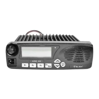
HM135 Service Manual
Preliminary version Page 2 of 13
Contents
1 TECHNICAL SPECIFICATIONS......................................................................................................................3
1.1 Test methods.................................................................................................................................................................3
1.2 Specifications table .......................................................................................................................................................3
2 CIRCUIT DESCRIPTION .................................................................................................................................4
2.1 General information.......................................................................................................................................................4
2.2 Microprocessor/control ..................................................................................................................................................4
2.2.a PTT circuit ........................................................................................................................................................4
2.3 Front panel (head) circuitry ...........................................................................................................................................5
2.4 VCO / Synthesizer (PLL) ...............................................................................................................................................5
2.4.a Temperature-Compensated Crystal Oscillator (TCXO)....................................................................................5
2.4.b Voltage-Controlled Oscillators ..........................................................................................................................5
2.4.c Synthesizer.......................................................................................................................................................6
2.5 Transmitter ....................................................................................................................................................................6
2.5.a RF Power Amplifier...........................................................................................................................................6
2.5.b Antenna Switching............................................................................................................................................6
2.5.c Power control....................................................................................................................................................6
2.5.d Transmitter Audio Circuits ................................................................................................................................7
2.5.e Double-point modulation...................................................................................................................................7
2.6 Receiver ........................................................................................................................................................................7
2.6.a Receiver’s Front-End........................................................................................................................................7
2.6.b Local Oscillator (LO).........................................................................................................................................7
2.6.c Mixer.................................................................................................................................................................8
2.6.d FM Detector and Squelch.................................................................................................................................8
2.6.e Audio routing ....................................................................................................................................................8
2.6.f CTCSS/DCS signal routing ..............................................................................................................................8
2.6.g Selcall signal routing.........................................................................................................................................8
2.7 Signaling........................................................................................................................................................................8
2.7.a General.............................................................................................................................................................8
2.7.b CTCSS (Continuous Tone Coded Squelch System)/DCS (Digital Coded Squelch) ........................................9
2.7.c Selective call (Selcall) encoder.........................................................................................................................9
2.8 ON/OFF switch, rear connector and internal connectors ..............................................................................................9
2.8.a ON/OFF switch .................................................................................................................................................9
2.8.b Rear connector .................................................................................................................................................9
2.8.c Internal connectors (accessory board) .............................................................................................................9
3 ADJUSTMENTS ............................................................................................................................................10
3.1 General........................................................................................................................................................................10
3.2 Initial Settings ..............................................................................................................................................................10
3.3 Applying power for the first time. .................................................................................................................................10
3.4 Loading the Firmware..................................................................................................................................................11
3.5 Programming the radio................................................................................................................................................11
3.6 Setting the Power Amplifier Bias .................................................................................................................................11
3.7 Setting the frequency and VCO’s tuning. ....................................................................................................................12
3.8 Setting the RF POWER...............................................................................................................................................12
3.9 Setting of modulation...................................................................................................................................................12
3.10 Setting of the Squelch Level........................................................................................................................................13