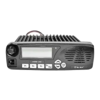
HM135 Service Manual
Preliminary version Page 3 of 13
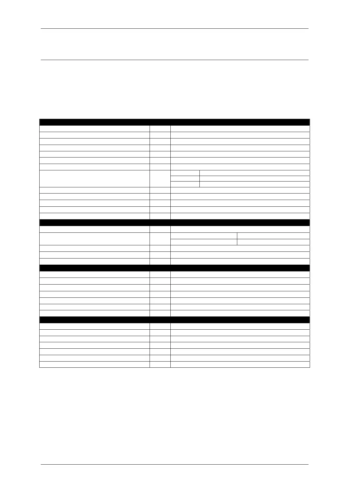
1 TECHNICAL SPECIFICATIONS
1.1 Test methods
ETS 300-086 / ETS 300-113 (optional “modem board”)
IEC 529 IP54 and MIL STD 810 C/D/E
1.2 Specifications table
General
Characteristic Units Value/Measurements conditions
Frequency MHz from 136 to 174
Operating Band MHz 38
Number of Programmable Channels - up to 100
Channel Spacing KHz 12.5 / 20 / 25
Frequency Steps KHz 5 / 6.25
Rated Power Supply Vcc 13.8
Stand-by 0.4 (or less)
RX 0.6 @ the maximum AF power
Current drain A
TX 5 (@ 25 W) / 3.5 (@ 10 W) / 2.4 (@ 4 W)
Antenna Impedance Ohm 50
Speaker Impedance Ohm 8
Frequency Stability ppm
±5
Operating Temperature Range °C from –25 to +55
Relative Humidity % 90 (non condensing)
Transmitter
Output Power (±1 dB)
W 10 / 25 (depending on the version)
from 9 KHz to 1 GHz
< -36 dBm Spurious Emissions
µW
from 1 to 4 GHz
< -30 dBm
Modulation System - FM (F3E) / PM (G3E)
Maximum Deviation KHz
± 2.5 (@ 12.5 KHz) / ±5 (@ 25 KHz)
Adjacent Channel Power Attenuation dB < -60 (@ 12.5 KHz) / -70 (@ 20-25 KHz)
Receiver
Configuration Double Conversion Superetherodyne
Sensitivity (at 12 dB SINAD)
µV
< 0.3
Squelch Sensitivity (SINAD)
µV
0.25 with 3 dB hysteresis
Selectivity (Adjacent Channel) dB At least -60 (@ 12,5 KHz) / -70 (@ 25 KHz)
Spurious Response Rejection dB > 70
Intermodulation dB > 65
Audio Output (1 KHz at 5% T.H.D.) W 4 (built-in internal speaker) / 10 (external audio output)
Mechanical Specifications
Type of construction - Metallic cabinet with detachable front panel
Size mm 180x57x28 with front panel / 174x48x150 main unit only
Weight Kg 1.4
Microphone connector - RJ
Rear I/O connector - 25-pins DB type
Shock resistance - Meets MIL STD 810 specifications
Moisture & Dust Resistance - According to the IEC529 and IP54 regulations