Do you have a question about the Alan HM135 and is the answer not in the manual?
Specifies the standards and methods used for testing the transceiver's performance.
Presents a detailed table of the transceiver's technical characteristics and parameters.
Provides an overview of the transceiver's circuit division into main board and head circuitry.
Details the function and operation of the microprocessor, including its monitoring and control capabilities.
Explains the Voltage Controlled Oscillators and Phase-Locked Loop synthesizer for frequency control.
Describes the temperature-compensated crystal oscillator providing the reference frequency.
Details the receive and transmit VCOs and their tuning mechanisms.
Explains the PLL IC and its role in frequency synthesis and phase-lock loop control.
Details the transmitter section, including power amplifier, antenna switching, and power control.
Details the three-stage RF power amplifier responsible for output power generation.
Describes the circuitry that switches the antenna between transmit and receive modes.
Explains how the output power is detected and regulated.
Details the audio path for speech and signaling signals in the transmitter.
Explains the modulation technique used for frequency and phase modulation.
Details the receiver section, including front-end, LO, mixer, and detector.
Describes the initial stages of the receiver, including filters and amplifiers.
Explains the local oscillator used for frequency conversion in the receiver.
Details the mixer stages responsible for frequency conversion in the receiver.
Describes the FM detector and squelch circuitry for signal demodulation and muting.
Explains how the audio signals are processed and routed to the speaker.
Details the routing of CTCSS/DCS signals for signaling functions.
Explains the routing of Selcall signals for selective calling.
Covers signaling systems like CTCSS, DCS, and Selcall.
Introduces the signaling capabilities including ADC/DAC converters for tones.
Details the synthesis and decoding of CTCSS/DCS signals for squelch and signaling.
Explains the generation and decoding of Selcall signals for selective calling.
Describes power switch, rear I/O, and internal board connectors.
Describes the function and operation of the power ON/OFF switch.
Details the rear connector and its various connections for external devices.
Explains the internal connectors used for option boards and modules.
Lists the main trimmer potentiometers and capacitors in the unit for adjustment.
Provides initial settings for controls and components before powering on.
Guides on how to apply power safely for the first time after initial settings.
Instructions for loading firmware using a programmer via the JTAG connector.
Steps for programming the radio's channels and settings using a programming cable.
Procedure to adjust the bias for the transmitter driver and power amplifier stages.
Guides on setting the radio's frequency and tuning the VCOs for accurate operation.
Instructions on adjusting the transmitter's RF output power to the desired level.
Procedure for setting and verifying the radio's modulation deviation.
Steps to adjust the squelch level for proper noise muting and signal reception.
Provides important warnings and disclaimers regarding the manual's use and equipment.
Explains symbols, font conventions, and note types used throughout the manual.
Lists the items included in the programmer's software package.
Specifies the hardware and software needed to use the programming software.
Guides the user through the installation process of the programming software.
Explains how to connect the transceiver to the computer using the serial cable.
Instructions on how to start and launch the programming software.
Guides on selecting the correct serial port for communication with the radio.
Explains how to view the software version and other details via the 'About' menu.
Crucial steps for first-time users to restore the default signal database.
Addresses whether to create new data or use previously stored data for programming.
Instructions on how to create and save a new programming file.
Covers setting fundamental channel parameters like frequencies and power levels.
Details how to configure CTCSS and DCS settings for channels.
Explains how to navigate between the Channel Data and Global Data windows.
Describes the layout and areas within the Global Data window.
Guides on setting up receive parameters for selective calls, including sequences.
Details how to define transmit sequences for selective calls.
Covers defining RX standards and selecting received sequences for Selcal.
Explains how to define specific transmit calls like Call1, Call2, and Emergency.
Describes how the monitor function behaves and can be configured.
Details how to set manual or automatic reset for selective call functions.
Explains how to view a summary of all programmed channel parameters.
Allows customization of standard Selcal parameters or creation of personal standards.
Guides on configuring scan conditions, timings, and behavior.
Configures automatic Selcal transmission upon radio power-on.
Sets transmission time limits and PTT lock conditions to prevent misuse.
Specifies the maximum allowed transmission time per message.
Configures conditions for locking the PTT, such as carrier detection.
Allows enabling or disabling audible feedback for key presses and warnings.
Guides on configuring acoustic warning signals for received Selcalls.
Allows enabling or disabling the audio monitor for selective calls.
Configures radio behavior during emergency calls, including channel and transmission settings.
Adjusts LCD contrast, backlight, squelch, and other miscellaneous settings.
Allows customization of radio menus and assignment of functions to F keys.
Instructions for transferring programmed data from PC to the radio.
Guides on saving programmed data to a PC file for backup or cloning.
Explains how to restore the default signal database to factory settings.
Allows viewing the history log of programming sessions.
Instructions on how to properly close the programming software.
Covers opening existing data files or modifying radio data for cloning.
| Brand | Alan |
|---|---|
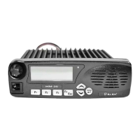
| Model | HM135 |
| Category | Transceiver |
| Language | English |