EasyManua.ls Logo

Alinx AXU2CGB-E - Page 20

Alinx AXU2CGB-E
57 pages
Print Icon
To Next Page IconTo Next Page
To Previous Page IconTo Previous Page
Loading...
AXU2CGB-E User Manual
20
/
57
www.alinx.com
Position
Model
Capacity
Factory
U19
FEMDRM008G-58A39
8G Byte
FORESEE
Table 2-5-1: eMMC FLASH Specification
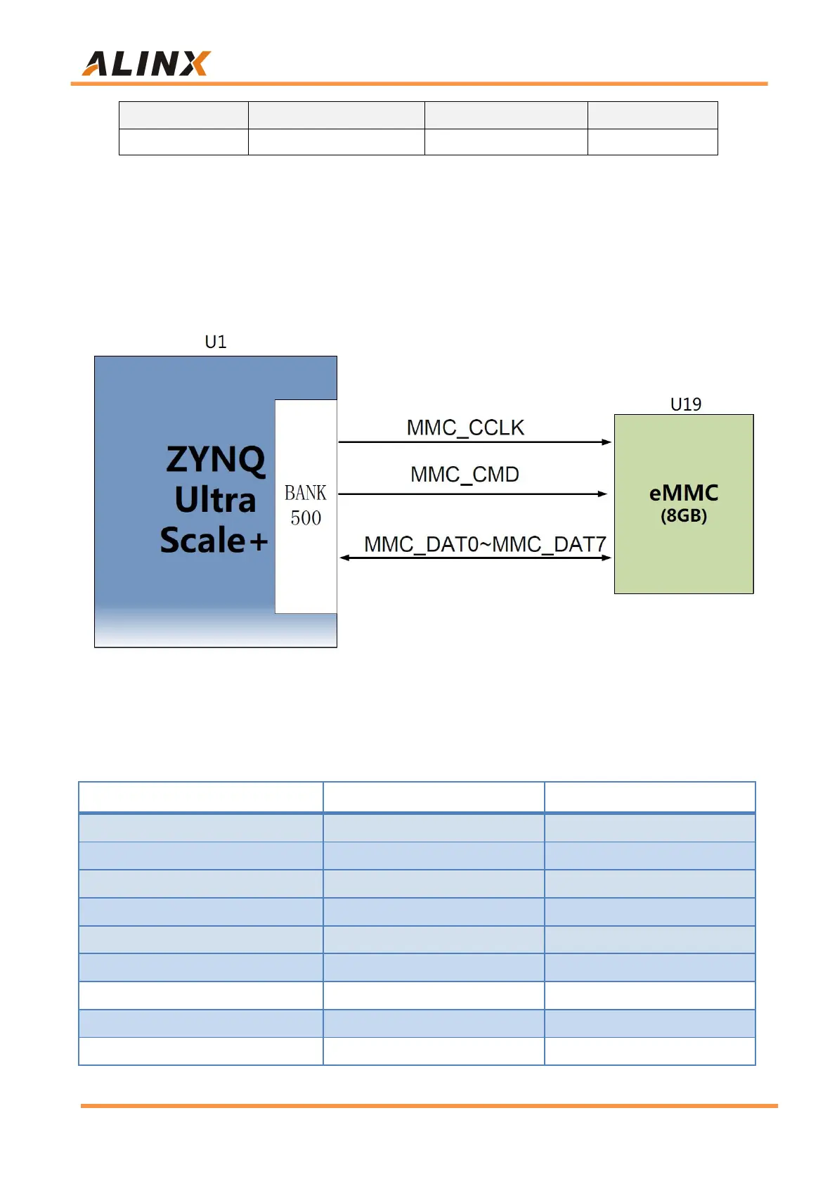
The eMMC FLASH is connected to the GPIO port of the BANK500 of the
PS part of the ZYNQ UltraScale+. In the system design, it is necessary to
configure the GPIO port function of the PS side as an EMMC interface. Figure
2-5-1 shows the part of eMMC Flash in the schematic diagram.
Figure 2-5-1: QSPI Flash in the schematic
Configuration Chip pin assignment:
Signal Name
Pin Name
Pin Number
MMC_DAT0
PS_MIO13_500
AH18
MMC_DAT1
PS_MIO14_500
AG18
MMC_DAT2
PS_MIO15_500
AE18
MMC_DAT3
PS_MIO16_500
AF18
MMC_DAT4
PS_MIO17_500
AC18
MMC_DAT5
PS_MIO18_500
AC19
MMC_DAT6
PS_MIO19_500
AE19
MMC_DAT7
PS_MIO20_500
AD19
MMC_CMD
PS_MIO21_500
AC21

Related product manuals