Motion Event Instructions
282 Rockwell Automation Publication MOTION-RM002H-EN-P-February 2018
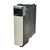
The 1756-OB16IS, 1732E-OB8M8SR, and 1756-OB16IEFS Scheduled Output
modules are designed to work in conjunction with the MAOC motion
instruction to provide position based output control (also known as PLS). The
MAOC instruction by itself allows position based output control by using the
position of any motion axis in ControlLogix, and CompactLogix for the
1732E-OB8M8SR module, as the position reference and any output or boolean as
the output. The MAOC updates the outputs based on motion axis position at the
motion group coarse update rate (typically 2ms to 10ms). The output turn-on and
turn-off times are determined by axis position and velocity.
To schedule the on/off times of the scheduled outputs of the module in
resolutions down to that rated for the module, outputs are scheduled as follows by
the available modules.
For the 1756-OB16IS, of 8 of its 16 outputs (outputs 0 to 7) in 100 μs increments.
Outputs are scheduled by entering data into one or more of the 16 schedules
provided by the output connection data store.
For the 1732E-OB8M8SR, of 8 of its 8 outputs (outputs 0 to 7) in 100 μs
increments. Outputs are scheduled by entering data into one or more of the 16
schedules provided by the output connection data store.
For the 1756-OB16IEFS, of 16 of its 16 outputs (outputs 0 to 15) in 10 μs
increments. Outputs are scheduled by entering data into one or more of the 32
schedules provided by the output connection data store.
Important:
When using the 1756-OB16IS module with the MAOC instruction, make sure you use the default
Communication Format for the module, that is, Schedule Output Data Per Point. If you change the
Communication Format when the module is used with an MAOC instruction, an error may result.
Operation
Outputs are scheduled on a per point basis and each individual output point is
controlled by its own timestamp.
Individual schedules are created in the controller, stored in the output image table
for the module, and sent over the backplane or EtherNet/IP to the Scheduled
Output module. The schedule specifies a sequence count, the output point to be
associated with the schedule, the time at which an output value should be applied
to the physical output point, and the value to be applied at the scheduled time.
The I/O module receives and stores the schedule. The timestamp of each schedule
is monitored by the module. When a schedule has expired, that is, the current time
matches the scheduled timestamp, the output value is then applied to the
corresponding output bit. Timer hardware in the ASIC is used to optimize the
scheduling algorithm. This hardware also reduces the latency and jitter

 Loading...


