Rockwell Automation Publication 193-UM014C-EN-P - August 2016 13
Installation and Wiring Chapter 1
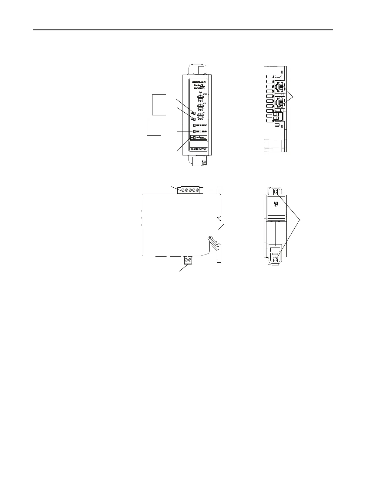
Features
Figure 1 - Features
Installation
The EtherNet/IP Communication Auxiliary Module may be DIN Rail or
panel mounted. To avoid overheating, the unit must be mounted vertically and
requires 37.4 mm (1-1/2 in.) of clearance at the top and bottom to allow
proper air flow. The temperature ratings for the unit are derated if the device is
not mounted in this manner.
Front View
Module
EtherNet/IP
Network
Front Port Link
Rear Port Link
DeviceNet Network
Status LED
Status
LEDs
Activity
LEDs
Earth Ground Connector
DIN
Rail Mounting
DeviceNet Connector
Panel Mounting
Ethernet Connectors
RJ-45
Side View
Rear View
Top View

 Loading...


