246 Rockwell Automation Publication 2094-UM001J-EN-P - March 2017
Appendix D Configure the Load Observer Feature
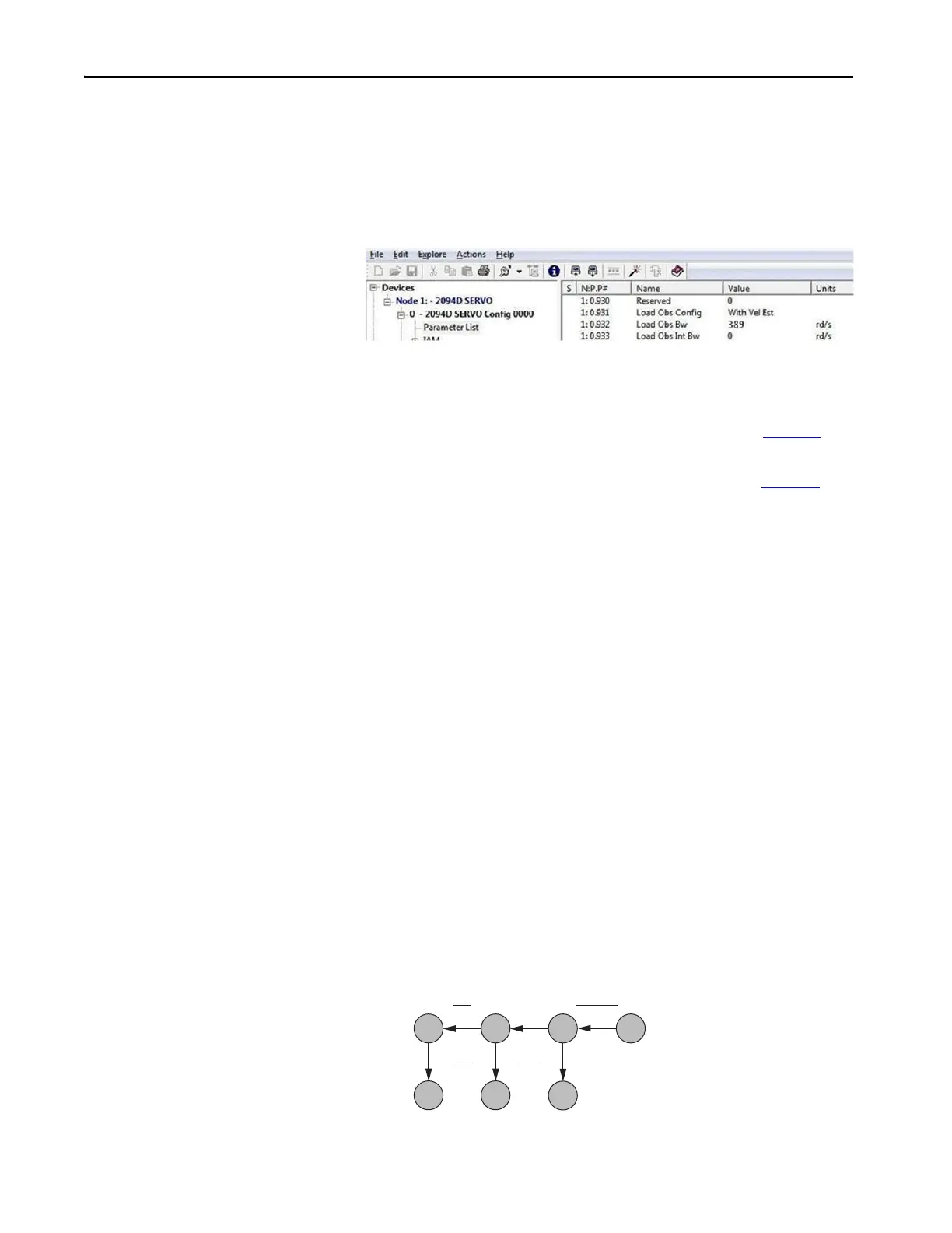
2. Configure these IDN parameter values.
a. IDN P-431 = 2 (Load Observer with Velocity Estimate)
b. IDN P-432 = Kop
c. IDN P-433 = 0
d. IDN P-065 = 1
3. If the Low-pass Output Filter is enabled, verify that the Low-pass
Output Filter Bandwidth is ≥ the Velocity Proportional Gain x 2/(2pi).
Sercos IDN P-065 has an impact on how the Low-pass Output Filter
functions. Refer to Torque Low-pass Filter Bandwidth on page 241
for
more information.
4. Refer to Compensate for High Frequency Resonances on page 251
, to
tune-out resonant frequencies.
Compliant Mechanical Loads
The compliant setting reduces all of the gains by a factor of (Load Inertia Ratio
+1) and then calculates the Load Observer Bandwidth. Typically, this
reduction is too conservative, making the loop response sluggish and the error
too large. However, it does assure stability.
Follow these steps if the load is compliant.
1. Make the following calculations to de-tune all gains by a factor of the
(Load Inertia Ratio + 1):
a. Position Loop Bandwidth:
Kpp = Position Proportional Gain/(Load Inertia Ratio + 1)
b. Position Integral Bandwidth:
Kpi = Position Integral Gain/(Load Inertia Ratio + 1)
2
c. Velocity Loop Bandwidth:
Kvp = Velocity Proportional Gain/(Load Inertia Ratio + 1)
d. Velocity Integral Bandwidth:
Kvi = Velocity Integral Gain/(Load Inertia Ratio + 1)
2
e. Load Observer Bandwidth: Kop = Kvp
0
1
1
4z
2
1
4z
(R+1)
2
0, 0,
K
pp
K
pi
K
vi
K
vp
K
oi
K
op
K
pp
2
4000
K
vp
2
4000
T
bw
 Loading...


