Rockwell Automation Publication 2094-UM001J-EN-P - March 2017 245
Configure the Load Observer Feature Appendix D
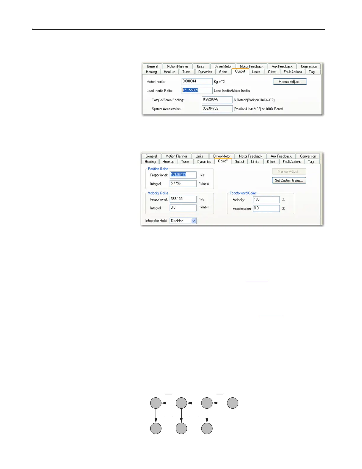
2. Click the Output tab in the Axis Properties dialog box and verify that
the Load Inertia Ratio > 0.
3. Click the Gains tab in the Axis Properties dialog box.
The current Position and Velocity gain values are used to recalculate
other gain values.
4. Determine if the mechanical load connected to the motor is rigid or
compliant.
• Rigid systems typically involve high-performance load mechanics
that are tightly coupled directly to the motor shaft and there is no lost
motion.
Refer to Rigid Mechanical Loads on page 245
, for rigid applications.
• Everything else is compliant, including systems with belts and
pulleys, long shafts, short shafts with heavy loads, and couplings and
gearboxes with backlash and/or lost motion.
Refer to Compliant Mechanical Loads on page 246
, for compliant
applications.
Rigid Mechanical Loads
Follow these steps if the load is rigid.
1. Calculate the Load Observer Bandwidth.
Load Observer Bandwidth: Kop = Velocity Proportional Gain
0
1
1
4z
2
1
4z
2
0, 0,
K
pp
K
pi
K
vi
K
vp
K
oi
K
op
K
pp
2
4000
K
vp
2
4000
T
bw
 Loading...


