Rockwell Automation Publication 5069-UM004A-EN-P - April 2019 275
Application and Wiring Examples for Safety Modules Appendix C
When the module is wired as shown, and the requirements listed are met in the
project of the safety controller, it is suitable for applications that are rated up
to, and including, Category 4 as defined in ISO 13849-1.
To achieve that suitability rating, the following requirements must be met:
• Point Mode must be Safety Pulse Test.
• Safety input pairs must be associated with different Test Output sources.
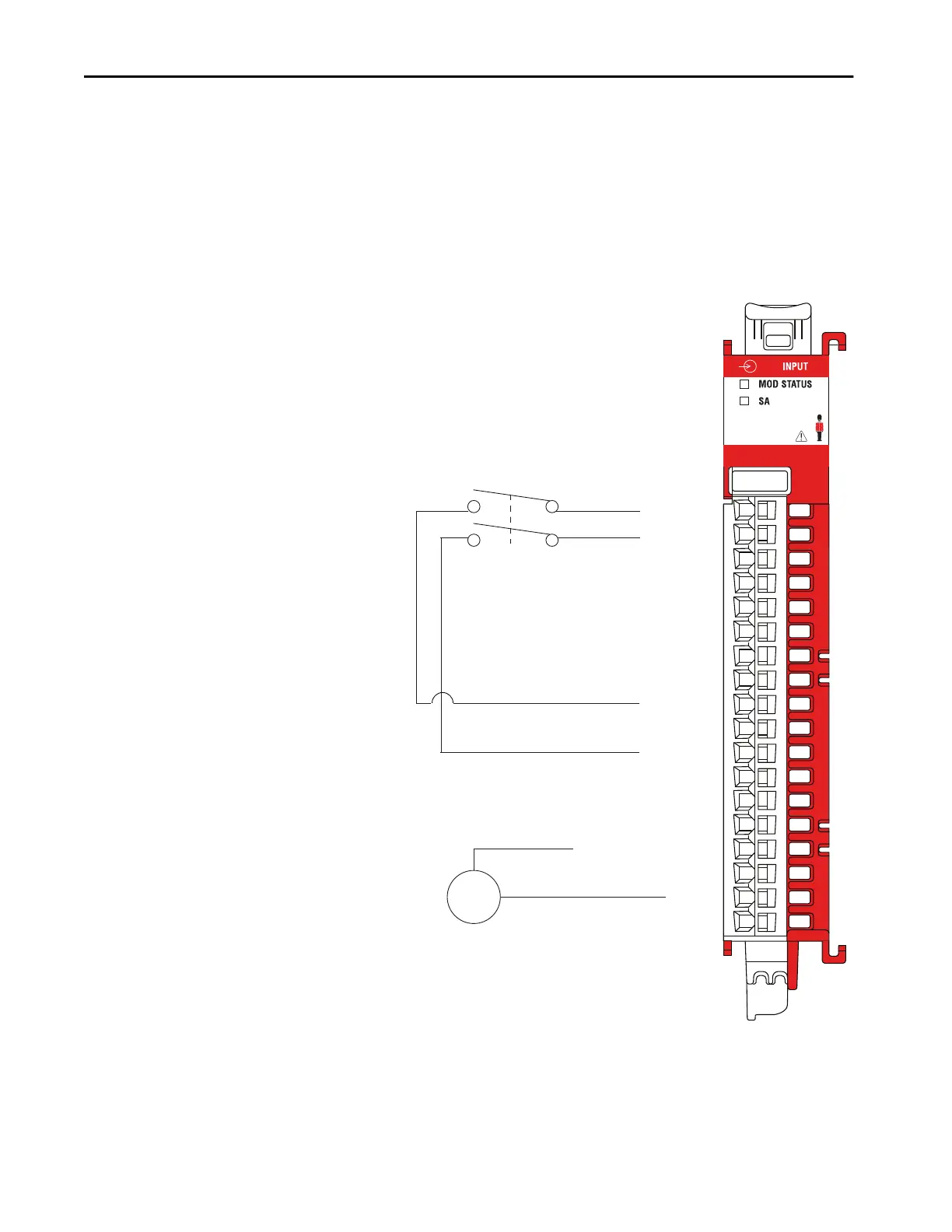
5069-IB8S
0
7
6
5
4
3
2
1
17
16
15
14
13
12
11
10
9
8
Muting
Lamp
Safety Input 0
Safety Input 1
Safety Input 2
Safety Input 3
Safety Input 4
Safety Input 5
Safety Input 6
Safety Input 7
Test Output 0
Test Output 0
Test Output 1
Test Output 1
Test Output/Muting Output 2
Test Output/Muting Output 2
Test Output/Muting Output 3
Test Output/Muting Output 3
COM
COM
IMPORTANT: When the power supply and muting lamp
are configured for a test output, you much connect the
return wire on the device to a COM point on the module.
Channel Connections
The diagram shows devices that are connected to safety
input channels 0 and 1, and to test outputs 2 and 3.
You are not restricted to using only those safety input
channels.
You can connect devices to any channel or combination
of channels as needed.
SA Power
Connections to an external power supply that provides
SA power via the SA Power RTB on one of the following:
• Compact GuardLogix 5380 controller
• 5069-AENTR or 5069-AEN2TR EtherNet/IP Adapter
• 5069-FPD field potential distributor
IMPORTANT: Remember the following:
• The 5069-IB8S and 5069-IB8SK modules use DC SA
power. You must connect DC power to the
component, that is, controller, adapter, or field
potential distributor, that provides SA Power to the
modules.
• If you install modules in a system that use AC SA
power and DC SA power, you must install them on
separate SA power buses.
• You use a 5069-FPD field potential distributor to
establish a new SA Power bus in a system. SA Power
buses are isolated from each other. To keep the
modules on separate SA Power buses, complete the
following steps.
1. Install the modules that use one type of SA power,
for example DC, to the right of the adapter or
controller, that is, the first SA Power bus.
2. Install the 5069-FPD field potential distributor to
establish a second SA Power bus.
3. Install the modules that use the other type of SA
power, for example AC, on the second SA Power
bus.
 Loading...


