Rockwell Automation Publication 5069-UM004A-EN-P - April 2019 277
Application and Wiring Examples for Safety Modules Appendix C
5069-OBV8S and
5069-OBV8SK Module
Wiring Diagrams
You can use the safety output modules in Bipolar mode or Sourcing mode.
Bipolar Mode
When the module is wired as shown, and the requirements listed are met in the
project of the safety controller, it is suitable for applications that are rated up
to, and including, Category 4 as defined in ISO 13849-1. To achieve that
suitability rating, the Point Mode must be Safety Pulse Test.
For Cat.4 applications, if your application remains in safe state, that is, the
output is off, for a prolonged duration, we recommend that you take one of the
following actions:
• Apply output monitoring at the actuator. The monitoring can be direct
or indirect.
• Limit the safe state to no more than 24 hours.
• Conduct functional test if safe state dwell time increases.
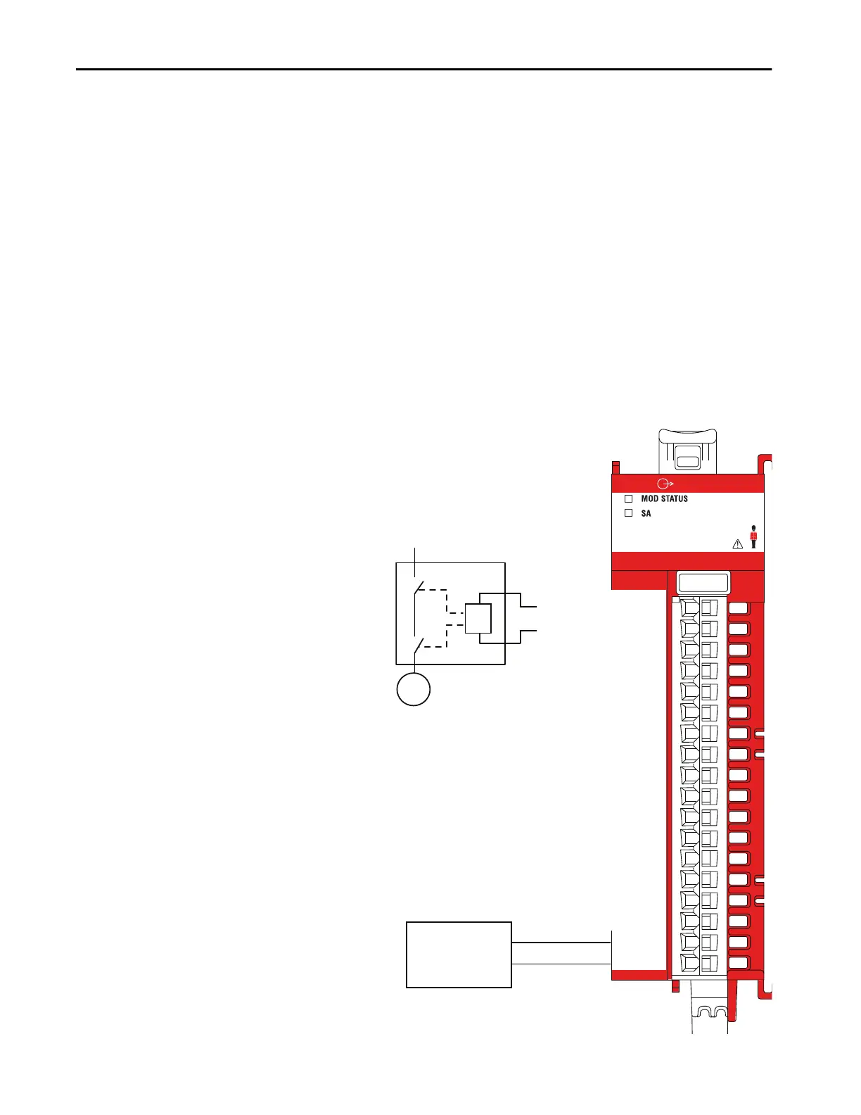
5069-OBV8S
OUTPUT
Safety Output 0 P (Sourcing)
LA +
LA –
Safety Output 3 P (Sourcing)
Safety Output 4 P (Sourcing)
Safety Output 4 N (Sinking)
Safety Output 1 N (Sinking)
Safety Output 5 P (Sourcing)
Safety Output 5 N (Sinking)
Safety Output 6 P (Sourcing)
Safety Output 6 N (Sinking)
Safety Output 7 P (Sourcing)
Safety Output 7 N (Sinking)
Safety Output 3 N (Sinking)
Safety Output 2 N (Sinking)
Safety Output 2 P (Sourcing)
Safety Output 1 P (Sourcing)
Safety Output 0 N (Sinking)
K
M
Actuator
Channel Connections
This wiring example shows connections to the P-N pair for Safety
Output 0. You are not limited to using channel 0 in this mode. You
can use all channel pairs as determined by your application.
24V DC
SELV/PELV-listed
power supply –
+
LA Power
The Local Actuator (LA+ and LA –) power connections are used to
supply field-side power to the module.
• The 5069-OBV8S and 5069-OBV8SK modules do not draw
current from the SA Power bus. The modules are DC type
modules. Therefore, you must install them on an SA Power bus
that uses DC power.
• If you install modules in a system that use AC SA power and DC SA
power, you must install them on separate SA power buses.
• You use a 5069-FPD field potential distributor to establish a new
SA Power bus in a system. SA Power buses are isolated from each
other. To keep the modules on separate SA Power buses, complete
the following steps.
1. Install the modules that use one type of SA power, for example
DC, to the right of the adapter or controller, that is, the first SA
Power bus.
2. Install the 5069-FPD field potential distributor to establish a
second SA Power bus.
3. Install the modules that use the other type of SA power, for
example AC, on the second SA Power bus.
•We strongly recommend that if, you have a direct connection
between the safety output module and an input module and
those modules are powered by separate power supplies, that you
connect SA- and LA- together. This practice helps to eliminate
grounding float from disrupting diagnostics.
Connection Pairs
The terminals for each channel function as a Bipolar connection pair
when you use a 5069-OBV8S or 5069-OB8VSK module in Bipolar
switching mode. For example, the Safety Output 0 P (Sourcing)
terminal and Safety Output 0 N (Sinking) terminal are a Bipolar
connection pair. That is, they are a P-N pair.
When the module is in Bipolar switching mode, you must connect
the device to both terminals.
 Loading...


