Interpret the Attribute Tables
Rockwell Automation Publication MOTION-RM003I-EN-P - February 2018 165
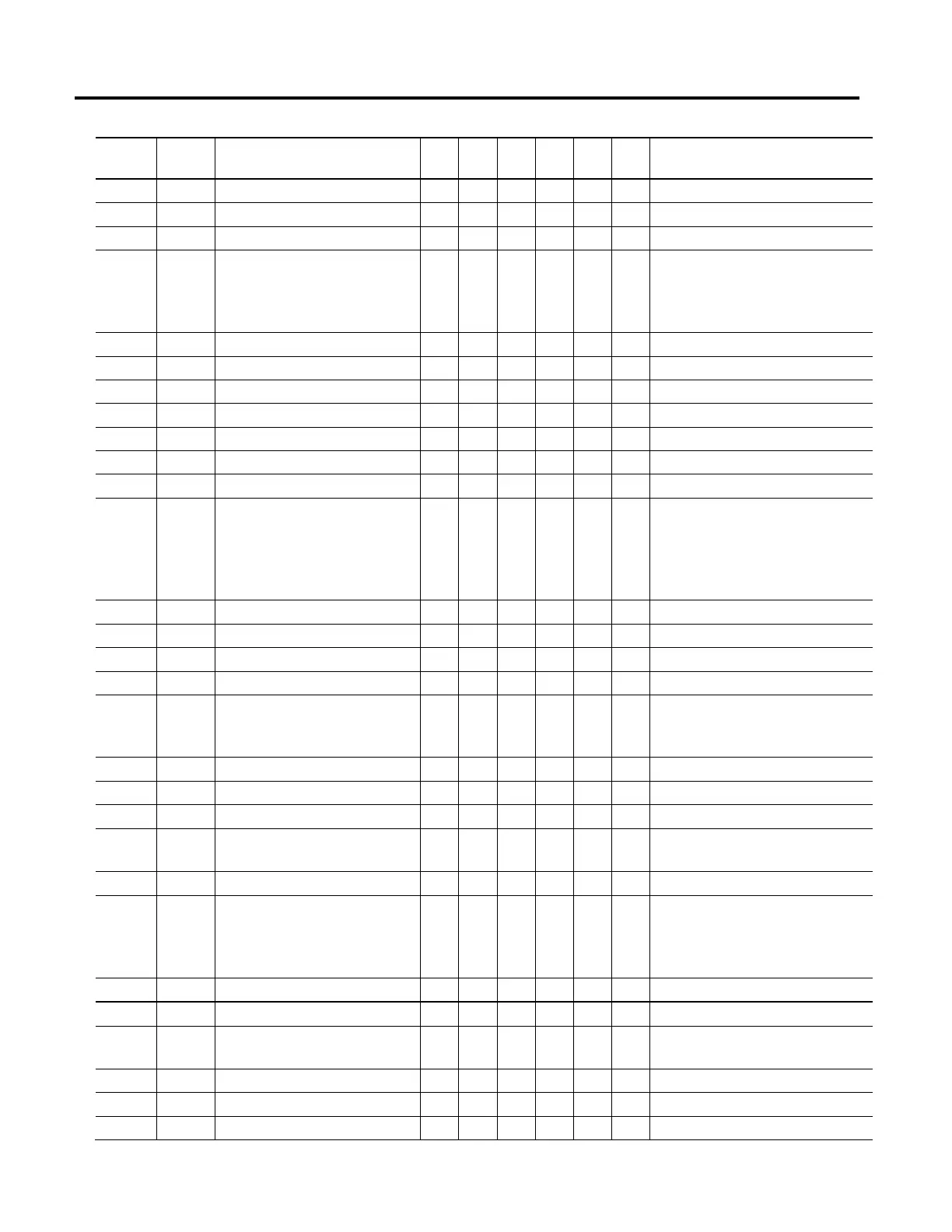
ID Access
Rule
Attribute B E F P V T Conditional Implementation
1351 Set Induction Motor Rotor Leakage Reactance - - Y Y Y N Ind Motor only, V24
1350 Set Induction Motor Rotor Resistance - - N N N N Ind Motor only
1348 Set Induction Motor Stator Leakage Reactance - - Y Y Y N Ind Motor only, V24
647 Set Inverter Overload Action - - Y Y Y N O-Enum
1 = Current Foldback (Y)
128 = Reduce PWM Rate (Y)
129 = PWM Foldback (Y)
699 Set Inverter Thermal Overload User Limit - - N N N N
1338 Set Linear Motor Damping Coefficient - - N N N N Linear Motor only
2313 Set Linear Motor Integral Limit Switch - - N N N N Linear Motor only
1336 Set Linear Motor Mass - - N N N N Linear Motor only
1337 Set Linear Motor Max Speed - - N N N N Linear Motor only
801 Get Load Observer Acceleration Estimate - - - N N N
806 Set Load Observer Bandwidth - - - N N N
805 Set Load Observer Configuration - - - N N N O-Enum
1 = Load Observer Only (N)
2 = Load Observer with Velocity Estimate (N)
3 = Velocity Estimate Only (N)
4 = Acceleration Feedback (N)
809 Set Load Observer Feedback Gain - - - N N N
807 Set Load Observer Integrator Bandwidth - - - N N N
802 Get Load Observer Torque Estimate - - - N N N
1370 Set Load Type - N N N N N DScale
750 Set Local Control N N N N N N O-Enum
1 = Conditionally Allowed (N)
2 = Allowed (N)
614 Set Mechanical Brake Control - - N N N N
616 Set Mechanical Brake Engage Delay - - N N N N
615 Set Mechanical Brake Release Delay - - N N N N
45 Set Motion Scaling Configuration - R R R R R O-Enum
1 = Drive Scaling (N)
1310/251 Set Motor Catalog Number - - N N N N Dr NV
1313 Set Motor Data Source - - R R R R O-Enum
1 = Database (N)
2 = Drive NV (N)
3 = Motor NV (N)
1323 Set Motor Integral Thermal Switch - - N N N N
1324 Set Motor Max Winding Temperature - - N N N N
646 Set Motor Overload Action - - N N N N O-Enum
1 = Current Foldback (N)
1322 Set Motor Overload Limit - - Y Y Y N
695 Set Motor Overspeed User Limit - - Y Y Y N
694 Set Motor Phase Loss Limit - - N N N N V24

 Loading...


