Rockwell Automation Publication 2097-UM002D-EN-P - April 2017 109
Kinetix 350 Drive Safe Torque-off Feature Chapter 6
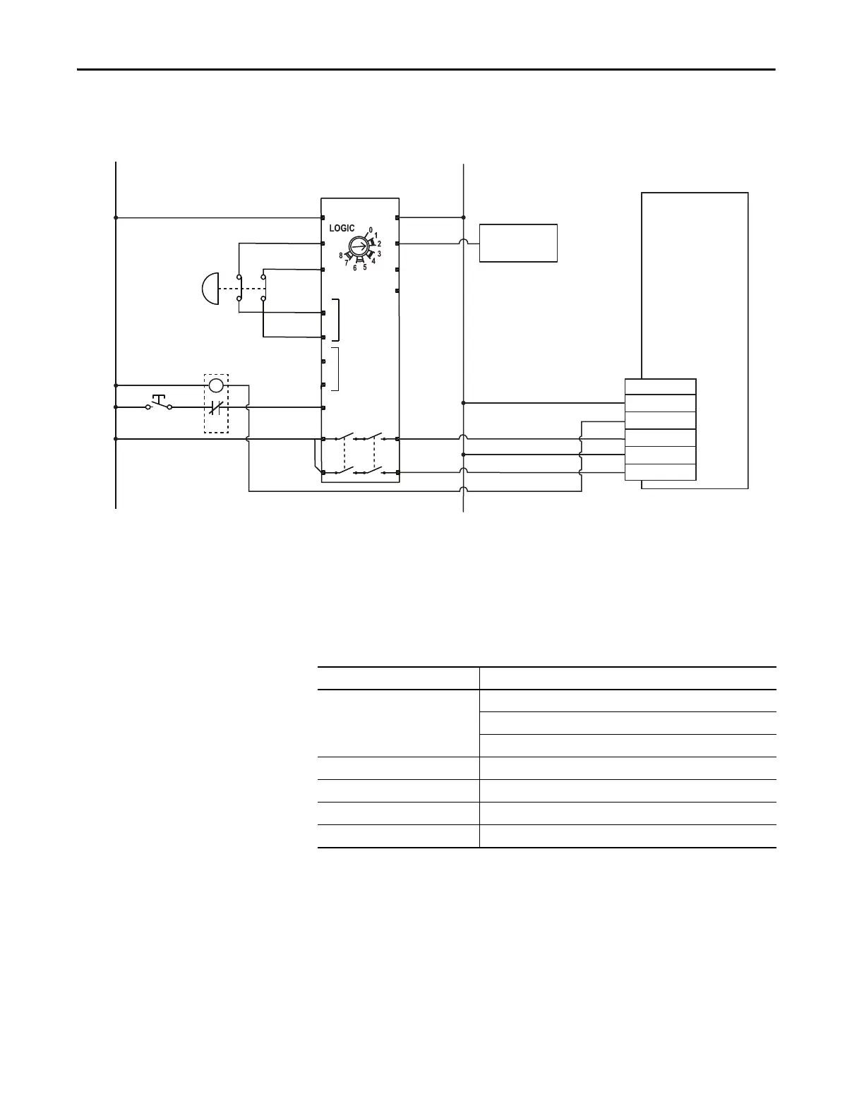
Figure 51 - Single-axis Relay Configuration (Stop Category 0) with Manual Reset
Safe Torque-off Signal
Specifications
This table provides specifications for the safe torque-off signals that are used in
the Kinetix 350 servo drives.
+24V DC
COM
Status
Safety Input 1
Safety Common
Safety Input 2
1
2
3
4
5
6
440R-D22R2
Input 1
DI
Input 2
A1
S11
S21
S12
S22
S32
S42
S34
13
23
A2
Y32
L12
L11
14
24
CR1
Reset
+
-
Kinetix 350 Drive
Safe Torque-off (STO)
Connector with
Wiring Header
External 24V COM
Safe Torque-off
Demand
External +24V
Allen-Bradley
Monitoring Safety Relay
MSR127RP (440R-N23135)
Auxiliary Signal
to PLC
Pins 1 and 2 are not used when using Safety Inputs.
Pin 3 is a sinking output.
Attribute Value
Safety inputs
(1)
(1) Safety inputs are not designed for pulse testing.
Insulated, compatible with single-ended output (+24V DC)
Enable voltage range: 20…24V DC
Disable voltage range: 0…1.0V DC
Input impedance 6.8 kΩ
Safety status Isolated Open Collector (Emitter is grounded.)
Output load capability 100 mA
Digital outputs max voltage 30V DC

 Loading...


