34 Rockwell Automation Publication 2097-UM002D-EN-P - April 2017
Chapter 3 Kinetix 350 Drive Connector Data
Kinetix 350 Drive Connectors
and Indicators
Although the physical size of the Kinetix® 350 drives vary, the location of the
connectors and indicators is identical.
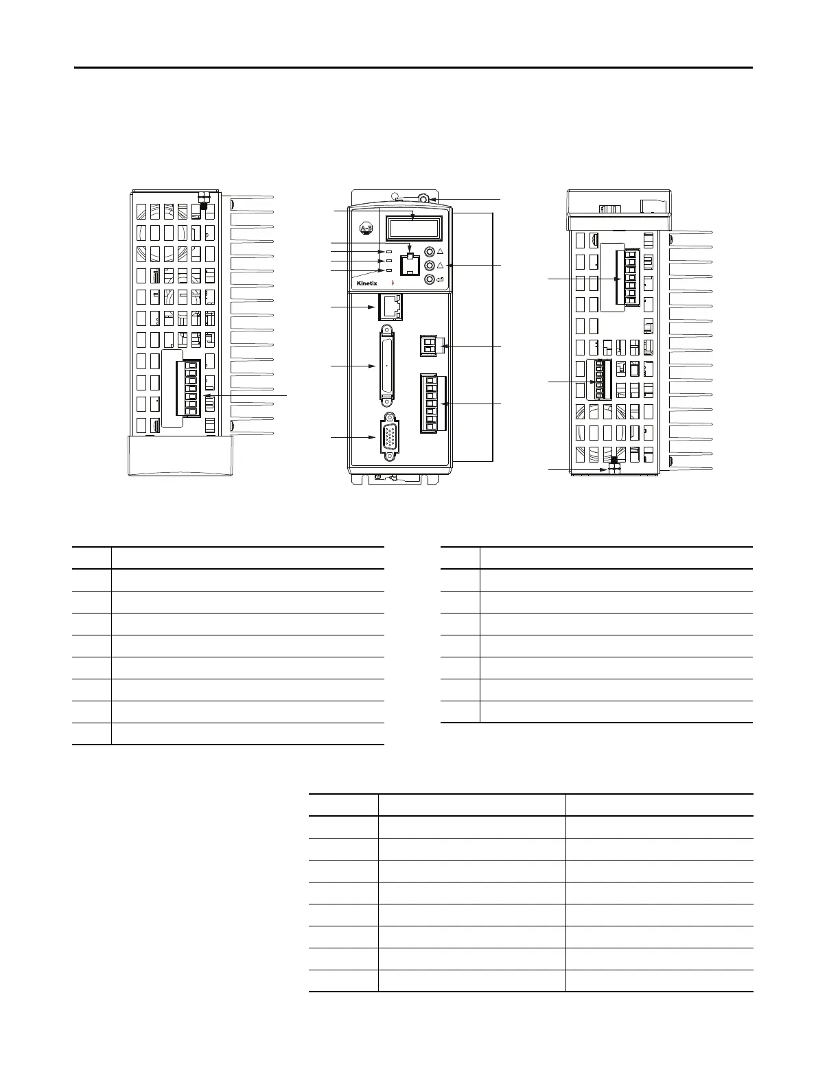
Figure 10 - Kinetix 350 Drive Connector and Indicators
Table 12 - Kinetix 350 Drive Connectors
Item Description Item Description
1 Mains (IPD) connector 9 Motor feedback (MF) connector
2 Data status indicator and diagnostic display 10 Ground lug
3 Memory module socket 11 Shunt resistor and DC bus (BC) connector
4 Network status indicator 12 Back-up power (BP) connector
5 Module status indicator 13 Display control push buttons (3)
6 Axis status indicator 14 Motor power (MP) connector
7 Ethernet communication port (Port 1) 15 Safe torque-off (STO) connector
8I/O (IOD) connector
10
3
4
2
5
6
7
9
8
1
12
13
11
14
15
10
0
Kinetix® 350 Drive, Front View
(2097-V33PR5-LM drive is shown)
Kinetix 350 Drive, Bottom View
(2097-V33PR5-LM drive is shown)
Kinetix 350 Drive, Top View
(2097-V33PR5-LM drive is shown)
Designator Description Connector
IPD AC input power 3-position or 4-position plug/header
PORT1 Ethernet communication port RJ45 Ethernet
IOD I/O SCSI 50-pin high-density connector
MF Motor feedback 15-pin high-density D-shell (male)
BP Back-up power 2-pin quick-connect terminal block
BC Shunt Resistor and DC Bus 7-pin quick-connect terminal block
MP Motor power 6-pin quick-connect terminal block
STO Safe torque off (STO) Terminal 6-pin quick-connect terminal block

 Loading...


