Rockwell Automation Publication 2097-UM002D-EN-P - April 2017 69
Connect the Kinetix 350 Drive System Chapter 4
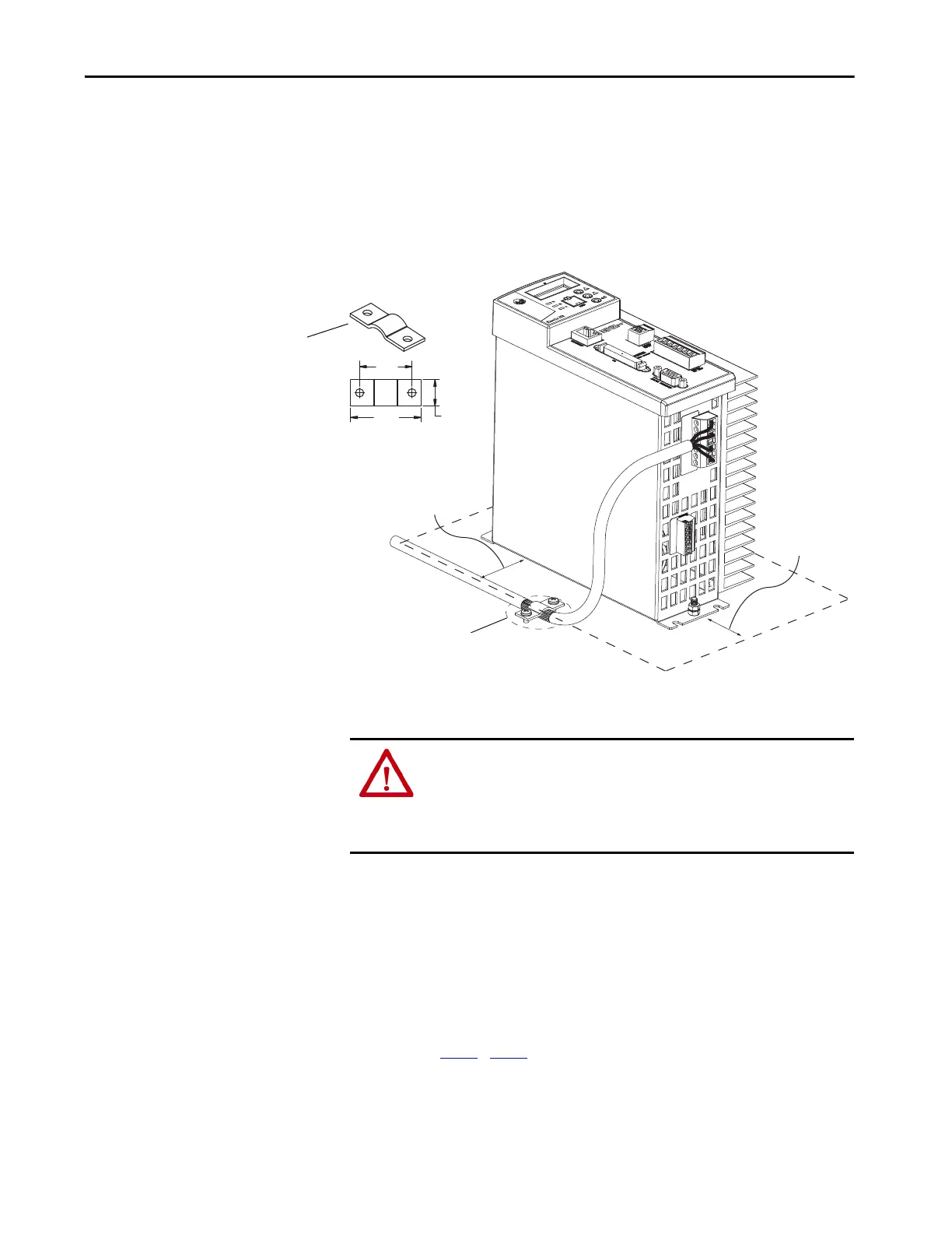
Apply the Motor Cable Shield
Clamp
This procedure assumes that you have completed wiring your motor power
(MP) connector and are ready to apply the cable shield clamp.
Follow these steps to apply the motor cable shield clamp.
1. Locate a suitable position for installing cable shield clamp within
50…75 mm (2…3 in.) of the drive.
2. Lay out and drill holes for cable clamp.
3. Locate the position on the motor power cable that comes under the
clamp and remove about an inch of the cable jacket to expose the shield
braid.
4. Position the exposed portion of the cable braid directly in line with the
clamp.
5. Clamp the exposed shield to the panel by using the clamp and two
#6-32 x 1 screws provided.
6. Repeat step 1
…step 5 for each Kinetix 350 drive you are installing.
50…75
(2…3)
50…75
(2…3)
34.0
(1.34)
25
(1.0)
12.7
(0.50)
If panel is painted, remove paint to
provide metal-to-metal contact.
Motor Power Ground
Shield Clamp
Dimensions are in mm (in.).
ATTENTION: Plan the installation of your system so that you can cut, drill,
tap, and weld with the system that is removed from the enclosure. Because
the system is of the open type construction, be careful to keep any metal
debris from falling into it. Metal debris or other foreign matter can become
lodged in the circuitry, which can result in damage to components.

 Loading...


