68 Rockwell Automation Publication 2097-UM002D-EN-P - April 2017
Chapter 4 Connect the Kinetix 350 Drive System
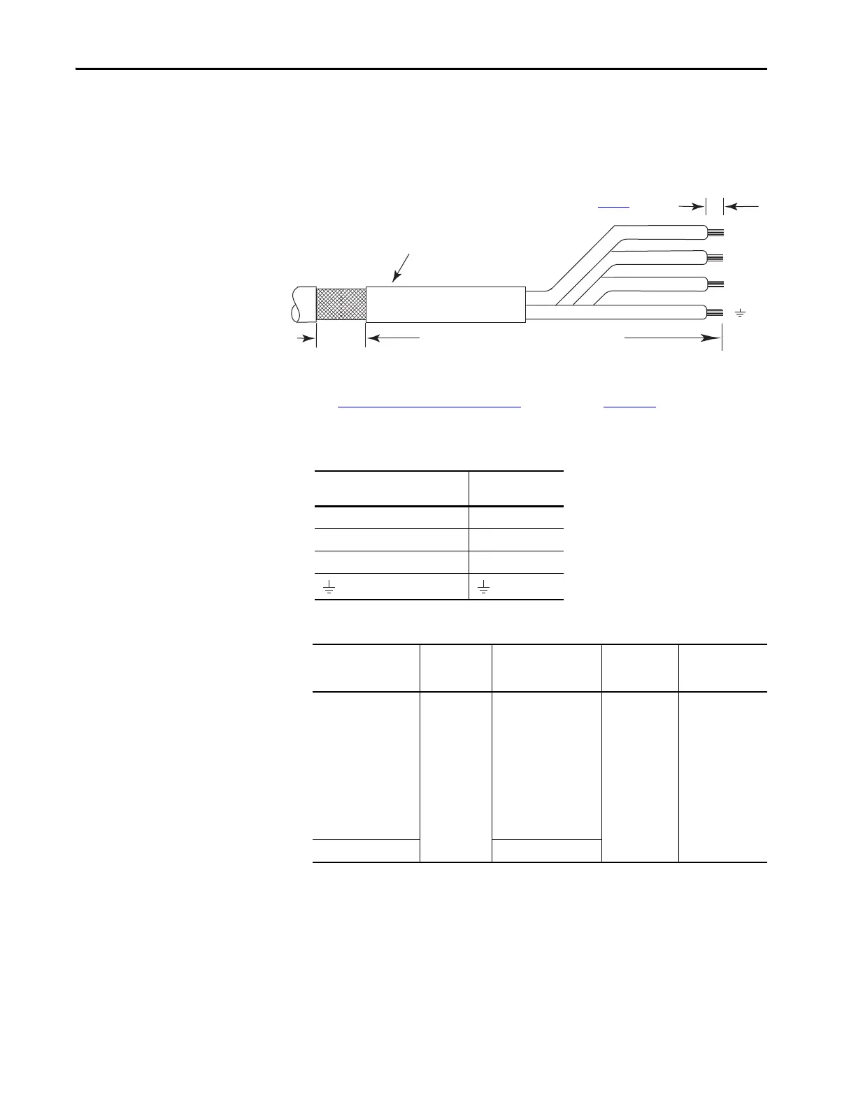
Cable shield and lead preparation are provided with most Allen-Bradley® cable
assemblies. Follow these guidelines if your motor power cable shield and wires
require preparation.
Figure 39 - Cable Shield and Lead Preparation
See Shunt Resistor Wiring Example that being on page 133 for interconnect
diagrams.
Table 29 - Motor Power (MP) Connector
Table 30 - Motor Power (MP) Termination Specifications
W
V
U
Motor Power Cable
Exposed Braid
25.4 mm (1.0 in.)
Outer Insulation
As required to have ground clamp within
50…75 mm (2…3 in.) of the drive.
Strip Length (See Ta bl e 30
)
MP-Series or TL-Series Servo
Motor
Terminal
U / Brown U
V / Black V
W / Blue W
Green/Yellow
Drive Cat. No. Terminals
Recommended
Wire Size
mm² (AWG)
Strip Length
mm (in.)
Torque Value
N•m (lb•in)
2097-V31PR0-LM
2097-V31PR2-LM
2097-V32PR0-LM
2097-V32PR2-LM
2097-V32PR4-LM
2097-V33PR1-LM
2097-V33PR3-LM
2097-V33PR5-LM
2097-V34PR3-LM
2097-V34PR5-LM
2097-V34PR6-LM
PE
W
V
U
2.5 (14)
7 (0.28) 0.5 (4.5)
2097-V33PR6-LM 4.0 (12)

 Loading...


