64 Rockwell Automation Publication 2097-UM002D-EN-P - April 2017
Chapter 4 Connect the Kinetix 350 Drive System
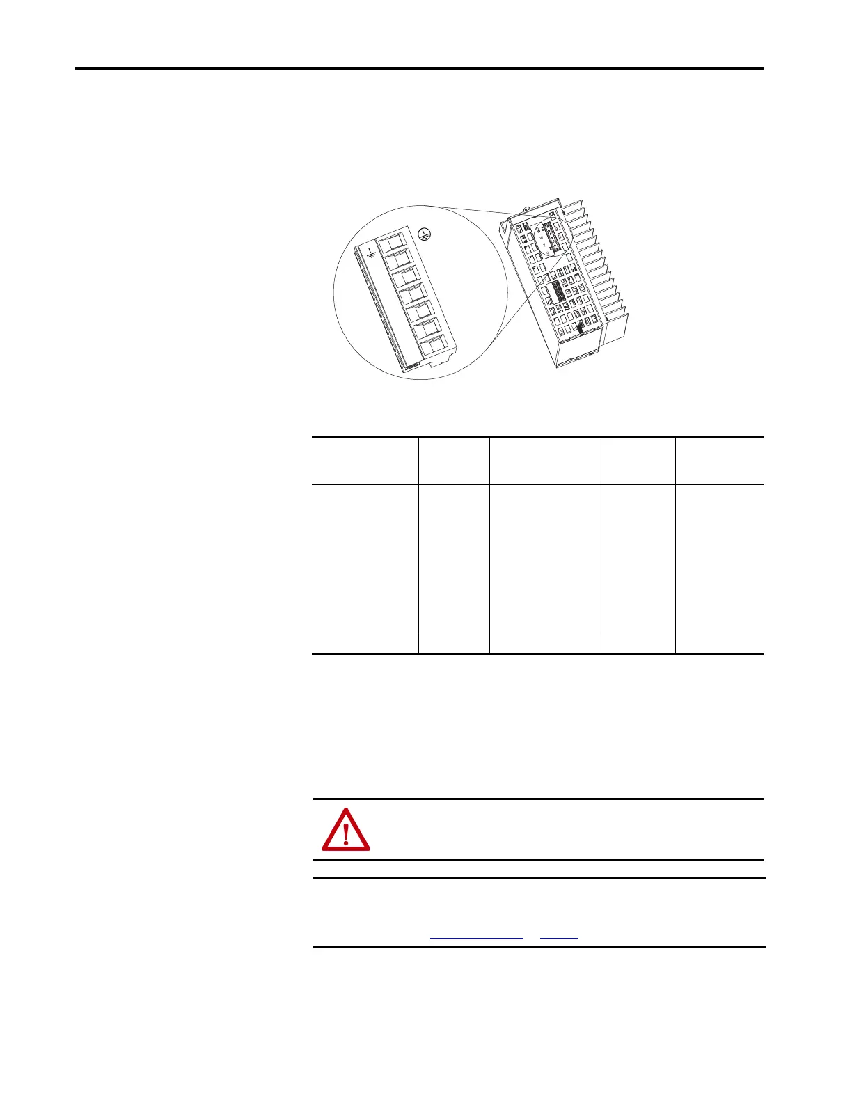
Wire the Motor Power (MP) Connector
Connections to the motor power (MP) connector include rotary motors and
rotary motor driven actuators.
Table 27 - Motor Power (MP) Termination Specifications
Cable Shield Terminations
Factory-supplied motor power cables for MP-Series™ and TL-Series™ motors
and actuator are shielded. The braided cable shield must terminate near the
drive during installation. Remove small portion of the cable jacket to expose
the shield braid and clamp the exposed shield to the panel.
Kinetix 350 Drive
Bottom View
Drive Cat. No. Terminals
Recommended
Wire Size
mm² (AWG)
Strip Length
mm (in.)
Torque Value
N•m (lb•in)
2097-V31PR0-LM
2097-V31PR2-LM
2097-V32PR0-LM
2097-V32PR2-LM
2097-V32PR4-LM
2097-V33PR1-LM
2097-V33PR3-LM
2097-V33PR5-LM
2097-V34PR3-LM
2097-V34PR5-LM
2097-V34PR6-LM
PE
W
V
U
2.5 (14)
7 (0.28) 0.5 (4.5)
2097-V33PR6-LM 4.0 (12)
ATTENTION: To avoid hazard of electrical shock, ensure shielded power
cables are grounded at a minimum of one point for safety.
IMPORTANT For TL-Series™ motors, also connect the 152 mm (6.0 in.) termination wire
to the closest earth ground.
See Pigtail Terminations
on page 65 for more information.

 Loading...


