Rockwell Automation Publication 2097-UM002D-EN-P - April 2017 67
Connect the Kinetix 350 Drive System Chapter 4
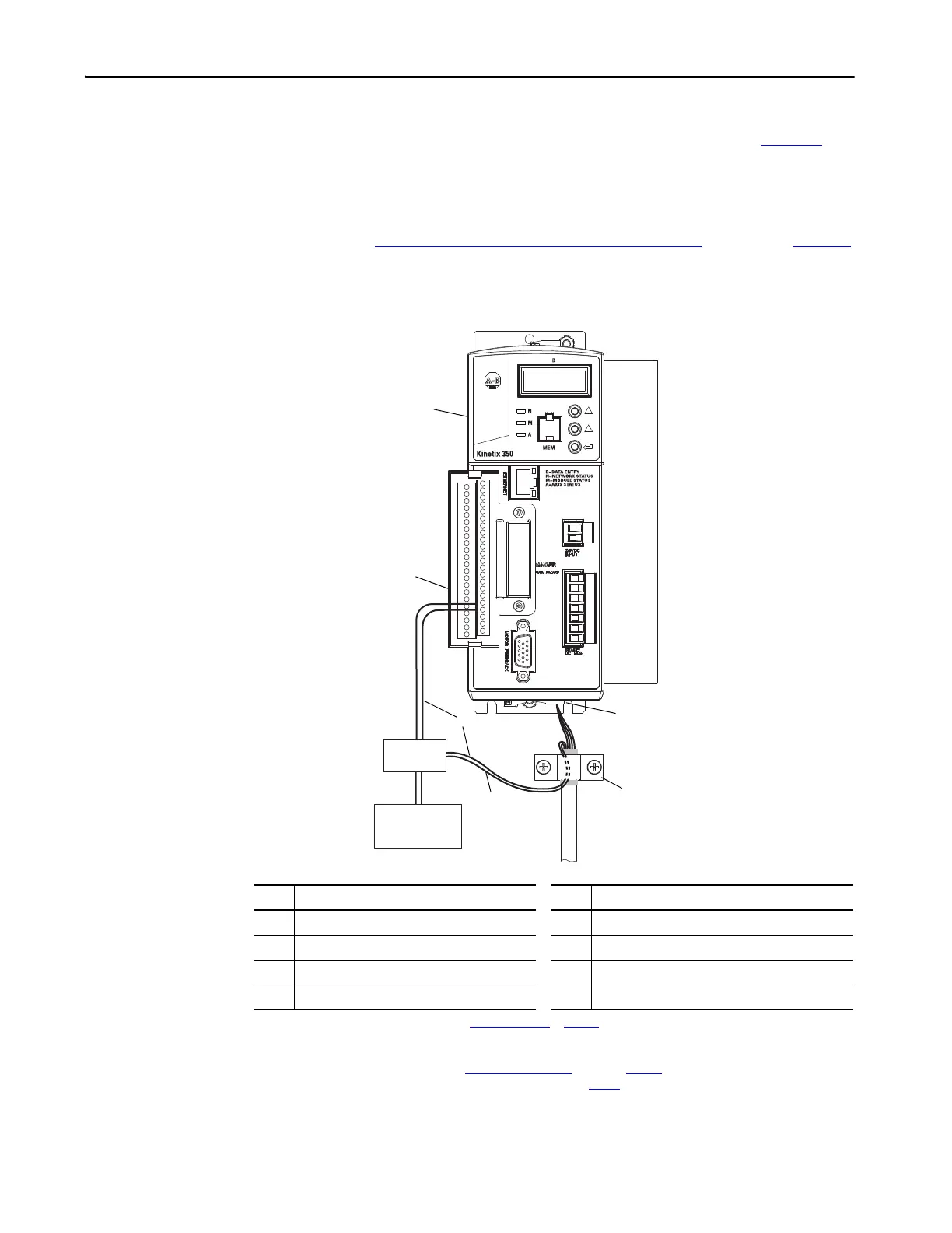
This diagram shows an example of wiring with three-phase power wires and
brake wires. The brake wires have a shield braid that is shown in Figure 38
as
gray, which folds back under the cable clamp before the conductors are
attached to the motor brake circuit. Thermal switch wires are included in the
feedback cable.
See Kinetix 350 Drive/Rotary Motor Wiring Examples
that begin on page 134
for interconnect diagrams.
Figure 38 - Motor Power Terminations (Three-phase and Brake Wires)
Item Description Item Description
1
(1)
24V power supply 5 I/O (IOD) connector
(2)
2
(1)
Relay and diode assembly
(3)
6 2097-V3xPRx-LM Kinetix 350 drive
3 Minimize unshielded wires in brake circuit 7 Motor power (MP) connector
4 MP-Series cable brake wires 8 Cable clamp
(4)
(1) User supplied. Size as required by motor brake, See Motor Brake Currents on page 140.
(2) Pins 43 and 44 are configured as MTR_ BRAKE+ and MTR_BRAKE- Common respectively. Wire the output as sourcing and set brake engage and
disengage times for motor selected. Motor brake is active on enable.
(3) Diode 1N4004 (1 A @ 400V DC) or equivalent. See Interconnect Diagram Notes
that being on page 131.
(4) Exposed shield under clamp and place within 50…75 mm (2…3 in.) of drive, see page 69
for details.

 Loading...


