66 Rockwell Automation Publication 2097-UM002D-EN-P - April 2017
Chapter 4 Connect the Kinetix 350 Drive System
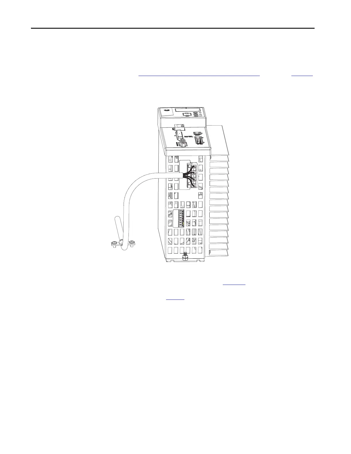
This diagram shows an example of three-phase power wires for motors/
actuators that have no brakes. Thermal switch wires are included in the
feedback cable.
See Kinetix 350 Drive/Rotary Motor Wiring Examples
that start on page 134
for interconnect diagrams.
Figure 37 - Motor Power Terminations (Only Three-phase Wires)
The cable shield clamp that is shown in Figure 37 is mounted to the subpanel.
Ground and secure the motor power cable in your system following
instructions on page 69
.
Motor Cable
Shield Clamp
Motor Power (MP) Connector Plug
Kinetix 350 Drive

 Loading...


