132 Rockwell Automation Publication 2097-UM002D-EN-P - April 2017
Appendix A Interconnect Diagrams
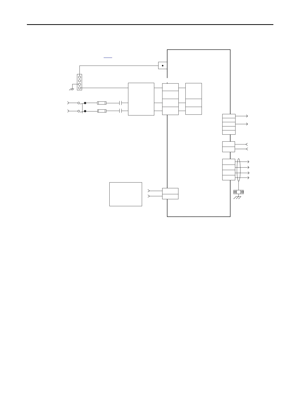
Figure 58 - Kinetix 350 Drives (240V Single-phase Input Power)
In this example, three-phase 240V AC is applied to 2097-V33PR x-LM drives
and 480V AC is applied to 2097-V34PRx-LM drives.
L1
L2/N
PE
N
L1
+24V DC
+
+
SH
-
-
EN
ACOM
29
26
U
V
W
PE
L2/N
PE
L1
L2
-24V DC
Single-phase AC Input
120/240V rms AC, 50/60 Hz
Notes 1, 2
Ground Stud
Fuse Disconnect
or Circuit Breakers
Input Fusing *
M1 *
Notes 5, 7
Use discrete logic or PLC
to control ENABLE to
drive.
Motor Power
(MP) Connector
I/O (IOD)
Connector
Note 4
2097-V31PRx-LM, 2097-V32PRx-LM
2097-V33PRx-LM and
Kinetix 350 Drive
* Indicates User Supplied Component
See table on page 130 for note information.
AC Line Filter
(Optional)
Note 3
Three-phase
Motor Power
Connections
Note 9
Cable Shield
Clamp
Note 8
Shunt Resistor
Connections
User-supplied
+24V DC
Back-up Power
(BP) Connector
Shunt Resistor
and DC Bus
(BC) Connector
Mains
Single-phase
AC Input
(IPD) Connector
Bonded Cabinet
Ground Bus *
2097-V31PRx-LM 2097-V32PRx-LM

 Loading...


