28 Rockwell Automation Publication 2097-UM002D-EN-P - April 2017
Chapter 2 Install the Kinetix 350 Drive System
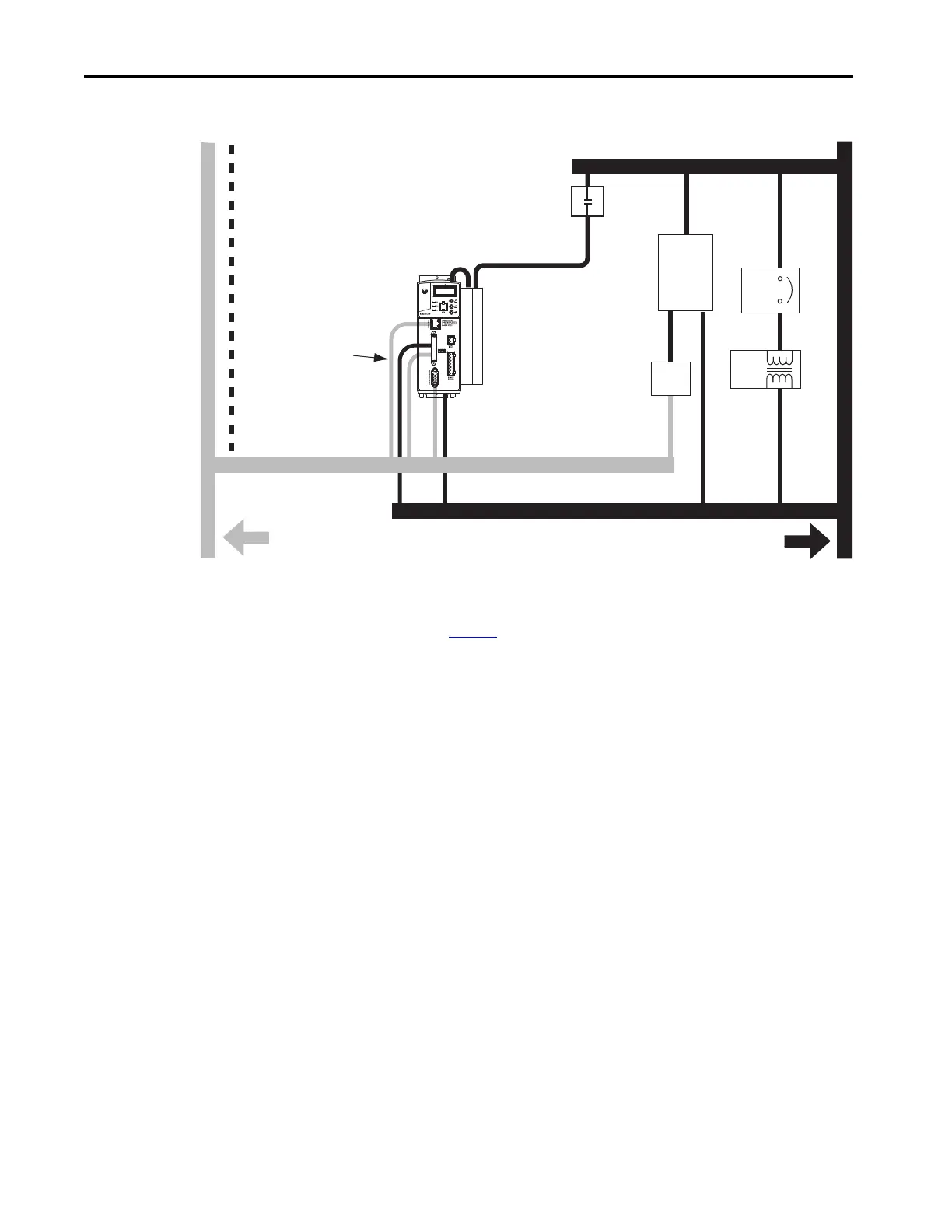
Figure 7 - Noise Zones (Bulletin 2097 AC line filters)
(1) If drive system I/O cable contains (dirty) relay wires, route cable in dirty wireway.
(2) For tight spaces, use a grounded steel shield. For examples, refer to the System Design for Control of Electrical Noise Reference
Manual, publication GMC-RM001
.
(3) This voltage is a clean 24V DC available for any device that requires it. The 24V enters the clean wireway and exits to the left.
(4) This voltage is a dirty 24V DC available for motor brakes and contactors. The 24V enters the dirty wireway and exits to the right.
Clean Wireway
24V Motor
Brake PS
Circuit
Breaker
Contactors
Kinetix 350
Drive
I/O
(1)
, Ethernet, and Feedback Cables
Very Dirty Zone
Segregated (not in wireway)
Route 24V DC I/O
Shielded Cable
Ethernet
(shielded)
Cable
I/O
(1)
, Motor Power, and Safety Cables
(4)
(3)
Dirty Wireway
XFMR
DC
Filter
Route encoder/analog/registration
shielded cables.
D
D
VD
VD
D
C
C
Bulletin 2097 AC line
filters mount to side,
as shown, or behind
the drive.
No sensitive
equipment within
150 mm (6.0 in.).
(2)

 Loading...


