Process Control Instructions
198 Rockwell Automation Publication 1756-RM006K-EN-P - November 2018
Description
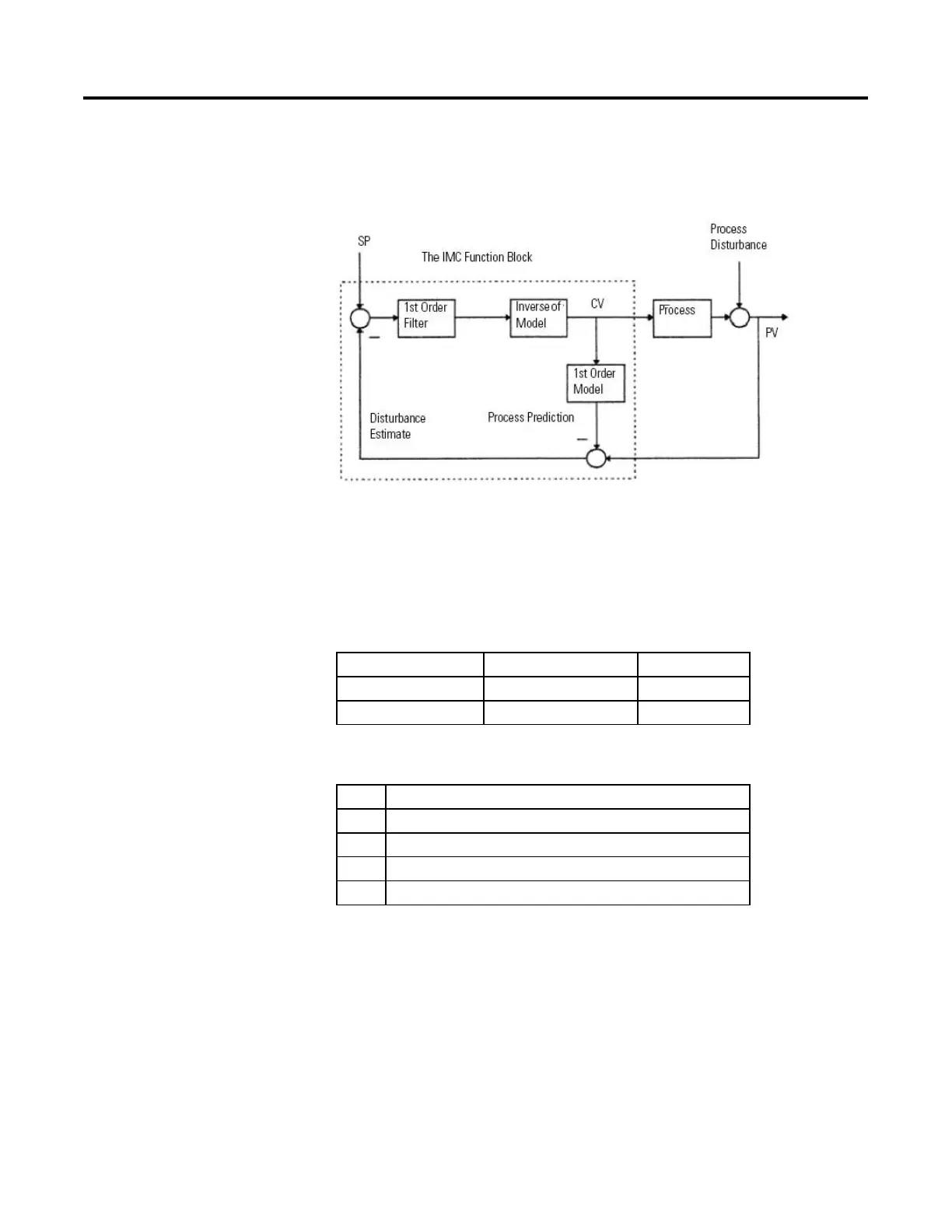
The following illustration shows the IMC function block configuration.
At each execution, the IMC function block compares the actual PV measurement
with PV prediction. The result is called disturbance estimate, which is the effect of
unmeasured process disturbances combined with the modeling imprecision. The
disturbance estimate is used as a bias for the setpoint of the control variable. In the
ideal case of no disturbances and perfect modeling, the disturbance estimate (the
feedback signal) becomes equal to zero.
First Order Model
M = K/(T*s+1)*exp(-D*s)
Inverse of Model
Inv = (T*s+1)/K
First Order Filter
F = 1/(e*s+1)
PV prediction = exp(-D*s)/(e*s+1) * (SP - Dist. estimate)
K...
Model gain
T... Model time constant
D... Model deadtime
e... Response time constant
s... Laplace variable
The function block then calculates the CV value (CVHLimit, CVLLimit, and rate
of change limits are imposed) and the PV prediction.
The IMC function block can be used in place of a PID function block with the
advantage over the PID control variable when controlling processes with large
deadtimes.
 Loading...

