Equipment Phase Instructions
432 Rockwell Automation Publication 1756-RM006K-EN-P - November 2018
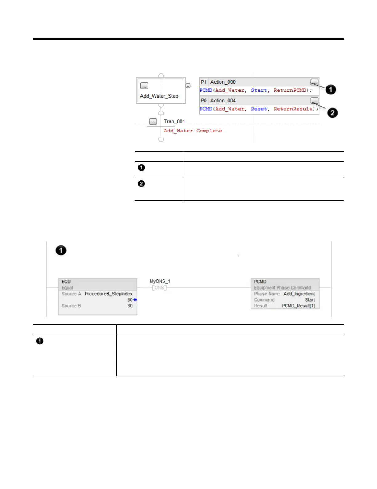
Structured Text
Number Description
When the SFC enters Add_Water_Step, change ADD_Water equipment phase to running
via the start command, The P1 qualifier limits this to the first scan of the step.
Before the SFC leaves Add_Water_Step (Add_Water_Complete = 1), change Add_Water
equipment phase to resetting via the reset command. The P0 qualifier limits this to the last
scan of the step.
Example 2
Ladder Diagram
Number Description
If ProcedureB_Stepindex = 30 (the routine is at step 30)
And this is the transition to step 30 (the ONS instruction signals that the EQU instruction went from false to true.)
Then
Change the state of the Add_Water equipment phase to running via the start command.
Verify that the command was successful and store the result code in PCMD_Result[1] [DINT Tag].
 Loading...

