Publication 1763-RM001C-EN-P - October 2009
Using the High-Speed Counter and Programmable Limit Switch 111
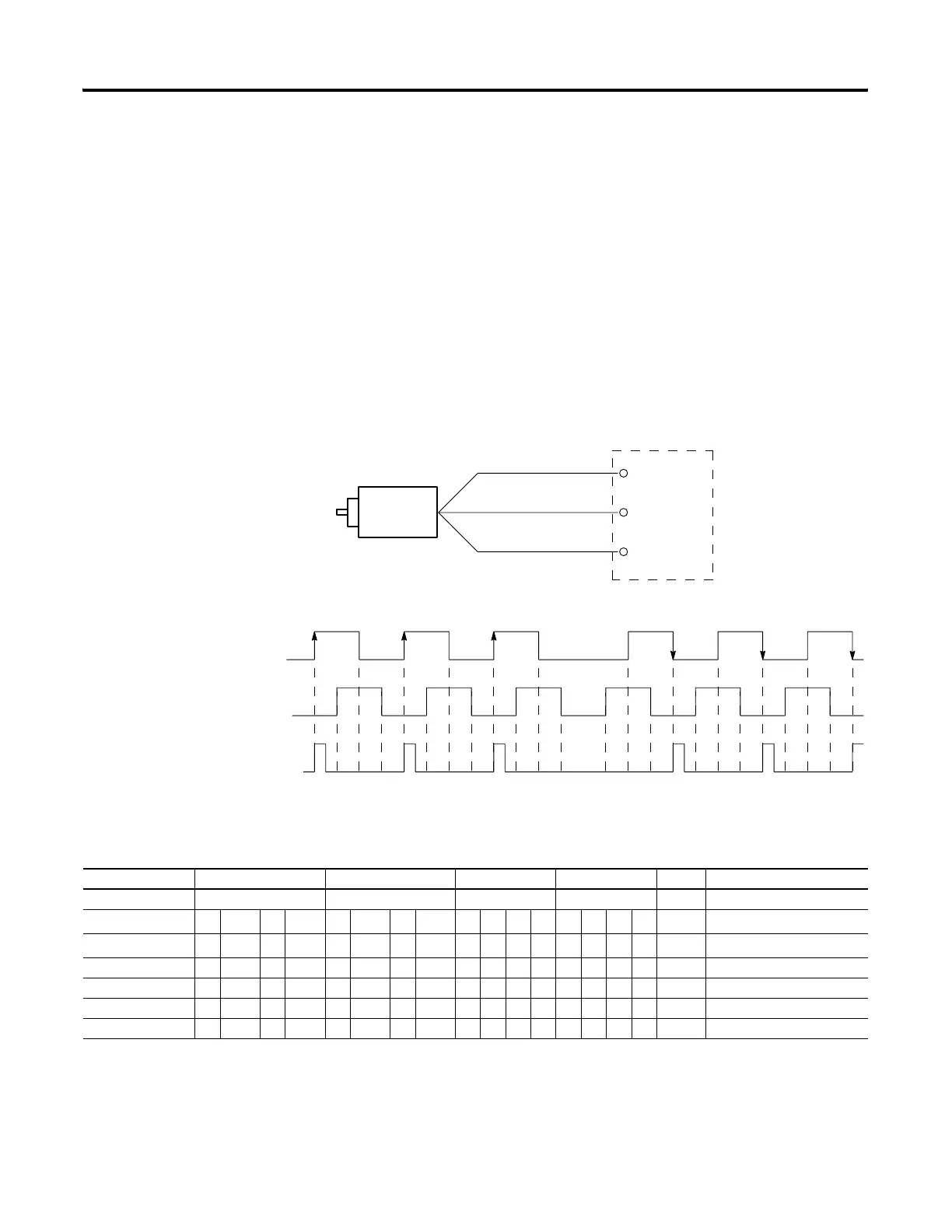
Using the Quadrature Encoder
The Quadrature Encoder is used for determining direction of rotation and
position for rotating, such as a lathe. The Bidirectional Counter counts the
rotation of the Quadrature Encoder.
The figure below shows a quadrature encoder connected to inputs 0, 1,
and 2. The count direction is determined by the phase angle between A
and B. If A leads B, the counter increments. If B leads A, the counter
decrements.
The counter can be reset using the Z input. The Z outputs from the
encoders typically provide one pulse per revolution.
HSC Mode 6 - Quadrature Counter (phased inputs A and B)
Quadrature Encoder
Input 0
Input 1
Input 2
A
B
Z
(Reset input)
Reverse Rotation
Forward Rotation
B
A
1
2
3
2
1
Count
HSC Mode 6 Examples
Input Terminals I1:0.0/0 (HSC0) I1:0.0/1 (HSC0) I1:0.0/2 (HSC0) I1:0.0/3 (HSC0) CE Bit Comments
Function Count A Count B Not Used Not Used
Example 1
(1)
⇑ off (0) on (1) HSC Accumulator + 1 count
Example 2
(2)
⇓ off (0) on (1) HSC Accumulator - 1 count
Example3 off (0) Hold accumulator value
Example 4 on (1) Hold accumulator value
Example 5 on (1) Hold accumulator value
Example 6 off (0) Hold accumulator value
(1) Count input A leads count input B.
(2) Count input B leads count input A.
Blank cells = don’t care,
⇑ = rising edge, ⇓ = falling edge
efesotomasyon.com - Allen Bradley,Rockwell,plc,servo,drive

 Loading...


