Publication 1763-RM001C-EN-P - October 2009
Function Files 53
RTA - Real Time Clock
Adjust Instruction
Instruction Type: output
The RTA instruction is used to synchronize the controllers Real-Time
Clock (RTC) with an external source. The RTA instruction will adjust the
RTC to the nearest minute. The RTA instruction adjusts the RTC based on
the value of the RTC Seconds as described below.
RTA is set:
• If RTC Seconds are less than 30, then RTC Seconds is reset to 0.
• If RTC Seconds are greater than or equal to 30, then the RTC
Minutes are incremented by 1 and RTC Seconds are reset to 0.
The following conditions cause the RTA instruction to have no effect on
the RTC data:
• RTC is disabled
• An external (via communications) message to the RTC is in progress
when the RTA instruction is executed. (External communications to
the RTC takes precedence over the RTA instruction.)
To re-activate the RTA instruction, the RTA rung must become false, and
then true.
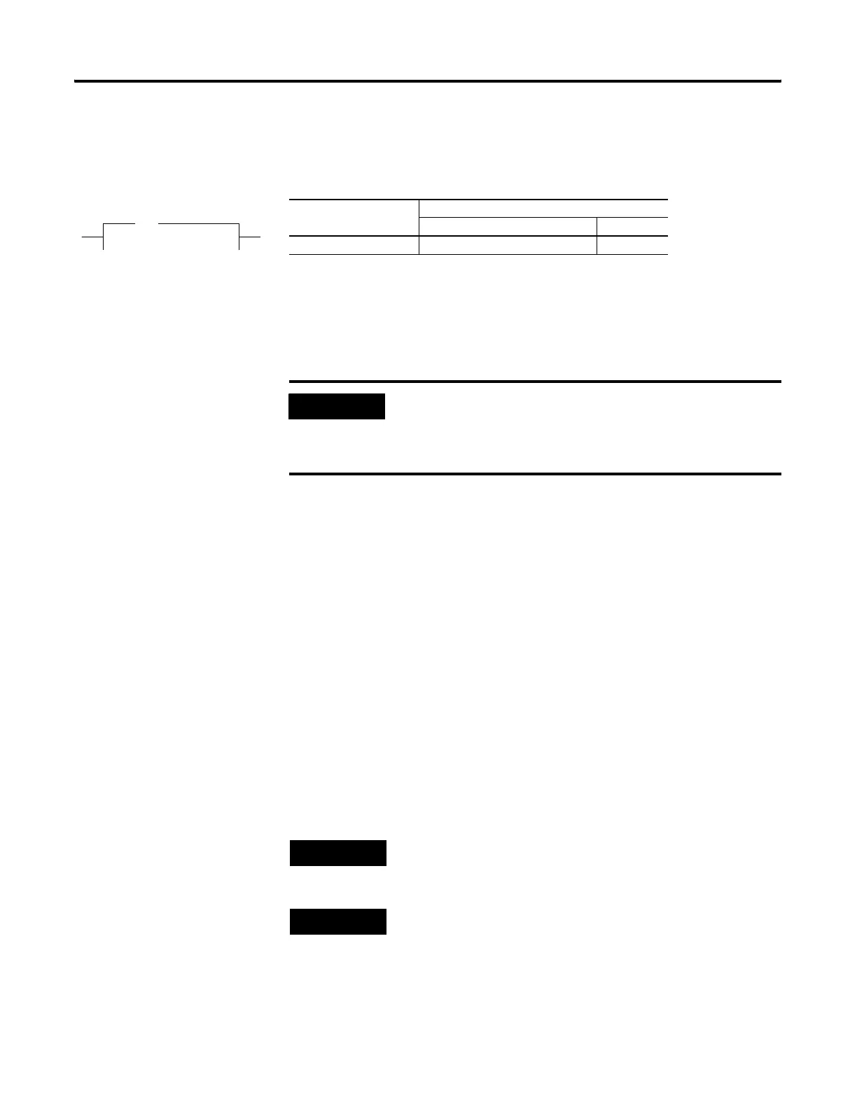
Execution Time for the RTA Instruction
Controller When Rung Is:
True False
MicroLogix 1100 4.37 µs 4.09 µs
IMPORTANT
The RTA instruction will only change the RTC when the
RTA rung is evaluated true, after it was previously false
(false-to-true transition). The RTA instruction will have
no effect if the rung is always true or false.
TIP
There is only one internal storage bit allocated in the
system for this instruction. Do not use more than one
RTA instruction in your program.
TIP
You can also use a MSG instruction to write RTC data
from one controller to another to synchronize time. To
send (write) RTC data, use RTC:0 as the source and the
destination.
RTA
Real Time Clock Adjust
efesotomasyon.com - Allen Bradley,Rockwell,plc,servo,drive

 Loading...


