Publication 1763-RM001C-EN-P - October 2009
314 ASCII Instructions
Addressing Control Files
The addressing scheme for the control data file is shown below.
ACL - ASCII Clear
Buffers
Instruction Type: output
(6) UL = Unload Bit - when this bit is set by the user, the instruction does not execute. If the instruction is already
executing, operation ceases. If this bit is set while an instruction is executing, any data already processed is sent to
the destination and any remaining data is not processed. Setting this bit will not cause instructions to be removed
from the ASCII queue. This bit is only examined when the instruction is ready to start executing.
(7) RN = Running Bit - when set, indicates that the queued instruction is executing.
(8) FD = Found Bit - when set, indicates that the instruction has found the end-of-line or termination character in the
buffer. (only used by the ABL and ACB instructions)
NOTE: The RN bit is not addressable
via the Control (R) file.
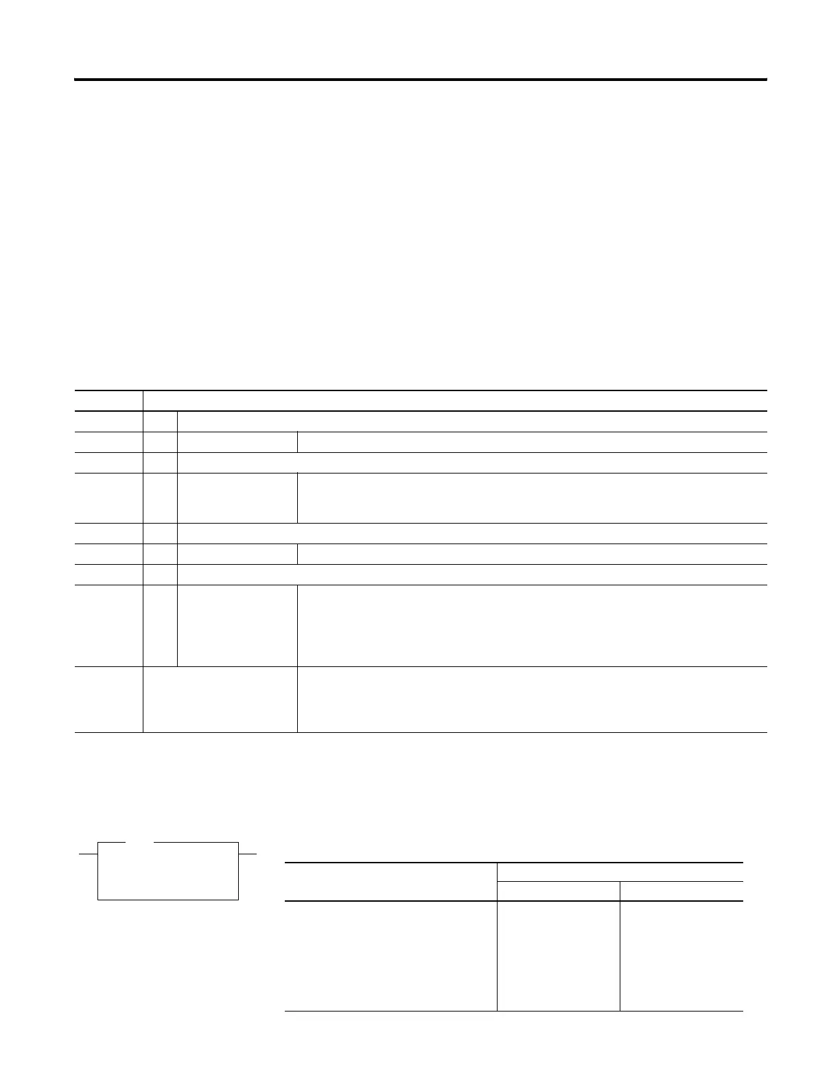
Format Explanation
R Control file
R:e.s/b f File number The valid file number range is from 3 to 255.
: Element delimiter
e Element number The valid element number range is from 0 to 255.
Each element is 3 words in length as shown in .
. Subelement delimiter
s Subelement number The valid subelement number range is from 0 to 2. You can also specify .LEN or .POS.
/ Bit delimiter
b Bit number The valid bit number range is from 0 to 15.
The bit number is the bit location within the string file element.
Bit level addressing is not available for words 1 and 2 of the control element.
Examples: R6:2
R6:2.0/13
R18:1.LEN
R18:1.POS
Element 2, control file 6
Bit 13 in sub-element 0 of element 2, control file 6
Specified string length of element 1, control file 18
Actual string length of element 1, control file 18
ACL
Ascii Clear Buffers
Channel 0
Transmit Buffer Yes
Receive Buffer No
ACL
Execution Time for the ACL Instruction
Controller When Instruction Is:
True False
MicroLogix 1100 clear buffers:
both 61.46 μs
receive 20.3 μs
transmit 23.2 μs
0.87 μs
0.87 μs
0.87 μs
efesotomasyon.com - Allen Bradley,Rockwell,plc,servo,drive

 Loading...


