Publication 1763-RM001C-EN-P - October 2009
252 Program Control Instructions
END - Program End
Instruction Type: output
The END instruction must appear at the end of every ladder program. For
the main program file (file 2), this instruction ends the program scan. For
a subroutine, interrupt, or user fault file, the END instruction causes a
return from subroutine.
MCR - Master Control
Reset
Instruction Type: output
The MCR instruction works in pairs to control the ladder logic found
between those pairs. Rungs within the MCR zone are still scanned, but
scan time is reduced due to the false state of non-retentive outputs.
Non-retentive outputs are reset when the rung goes false.
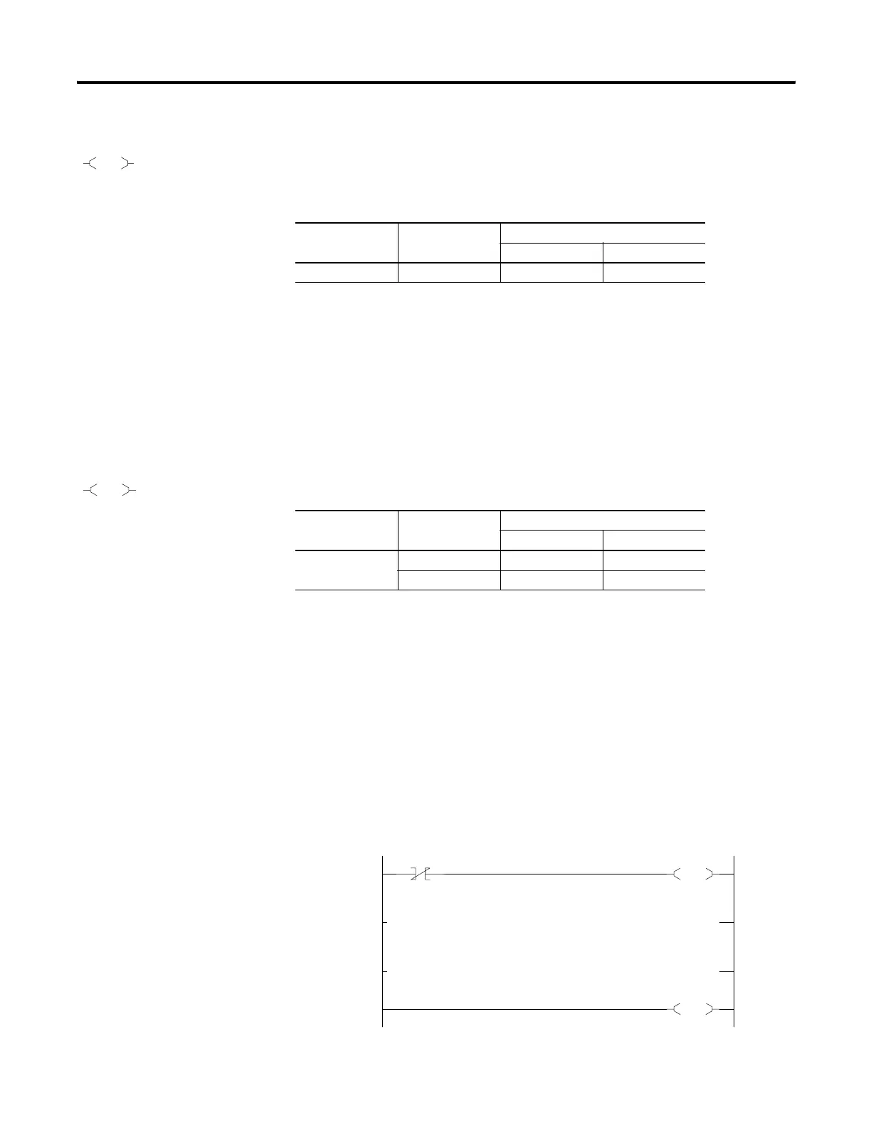
This instruction defines the boundaries of an MCR Zone. An MCR Zone is
the set of ladder logic instructions bounded by an MCR instruction pair.
The start of an MCR zone is defined to be the rung that contains an MCR
instruction preceded by conditional logic. The end of an MCR zone is
defined to be the first rung containing just an MCR instruction following a
start MCR zone rung as shown below.
END
Execution Time for the END Instruction
Controller Instruction When Rung Is:
True False
MicroLogix 1100 END 0.10 μs 0.10 μs
MCR
Execution Time for the MCR Instructions
Controller Instruction When Rung Is:
True False
MicroLogix 1100 MCR Start 1.12 μs 1.28 μs
MCR End 1.25 μs 1.12 μs
0030
I:1
0
MCR
0031
0032
0033
MCR
Ladder Logic within MCR Zone
efesotomasyon.com - Allen Bradley,Rockwell,plc,servo,drive

 Loading...


