Publication 1763-RM001C-EN-P - October 2009
82 Programming Instructions Overview
Using the Instruction
Descriptions
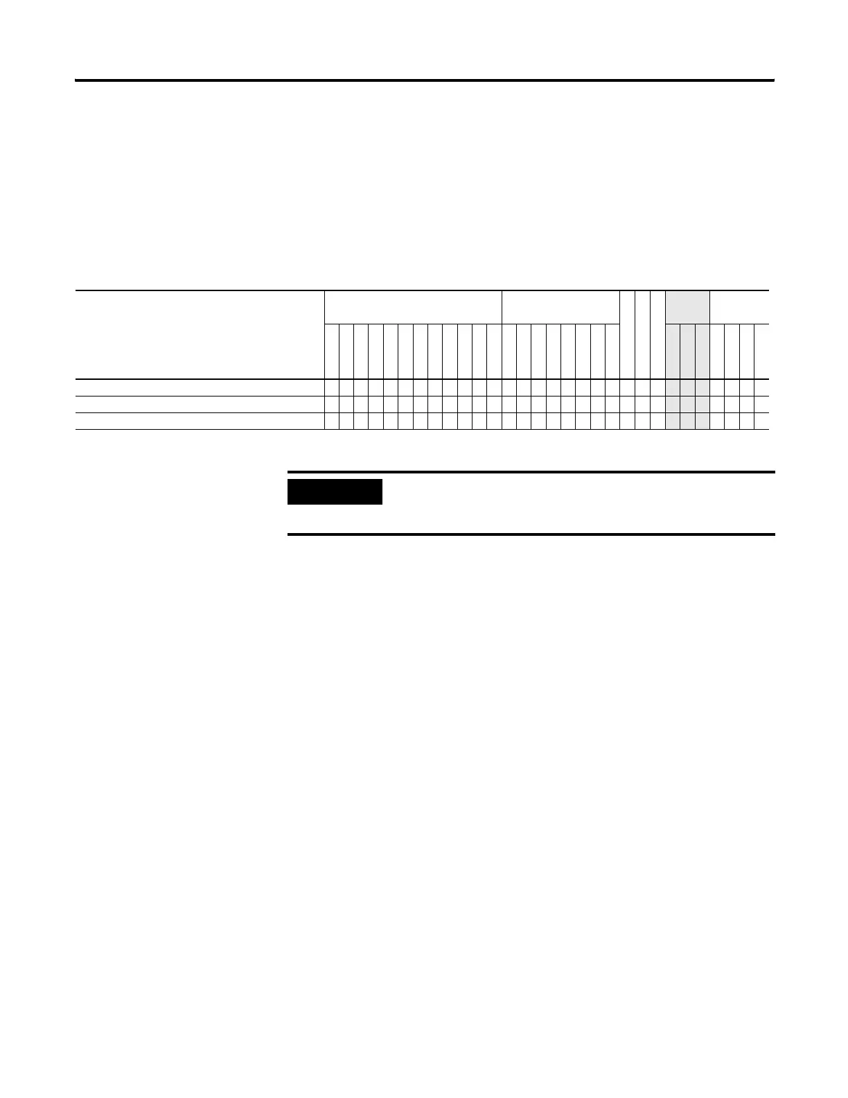
Throughout this manual, each instruction (or group of similar instructions)
has a table similar to the one shown below. This table provides
information for all sub-elements (or components) of an instruction or
group of instructions. This table identifies the type of compatible address
that can be used for each sub-element of an instruction or group of
instructions in a data file or function file. The definitions of the terms used
in these tables are listed below this example table.
The terms used within the table are defined as follows:
• Parameter - The parameter is the information you supply to the
instruction. It can be an address, a value, or an instruction-specific
parameter such as a timebase.
• Data Files - See Data Files on page 40.
• Function Files - See Function Files on page 49.
• CS - See Communications Status File on page 57.
• IOS - See Input/Output Status File on page 79.
• DLS - See Data Log Status File on page 440.
• Address Mode - See Addressing Modes on page 83.
• Addressing Level - Address levels describe the granularity at which
an instruction allows an operand to be used. For example, relay
type instructions (XIC, XIO, etc.) must be programmed to the bit
level, timer instructions (TON, TOF, etc.) must be programmed to
the element level (timers have 3 words per element) and math
instructions (ADD, SUB, etc.) must be programmed to the word or
long word level.
Valid Addressing Modes and File Types - Example Table
Parameter
Data Files Function Files
CS - Comms
IOS - I/O
DLS - Data Log
Address
Mode
(1)
Address
Level
O
I
S
B
T, C, R
N
F
ST
L
MG, PD
RI/RIX
PLS
RTC
HSC
PTO, PWM
STI
EII
BHI
MMI
LCD
Immediate
Direct
Indirect
Bit
Word
Long Word
Element
Source A •••••••••• ••••••••••••• • •••
Source B •••••••••• ••••••••••••
• • •••
Destination •••••••••• ••••••
• •••
(1) See Important note about indirect addressing.
IMPORTANT
You cannot use indirect addressing with: S, ST, MG, PD,
RTC, HSC, PTO, PWM, STI, EII, BHI, MMI, CS, IOS, and
DLS files.
efesotomasyon.com - Allen Bradley,Rockwell,plc,servo,drive

 Loading...


