Publication 1763-RM001C-EN-P - October 2009
544 Knowledgebase Quick Starts
# 17447 “Quick Start”
High Speed Counter
(HSC)
General Information
The MicroLogix 1100 has one 20Khz high-speed counter. The counter
has four dedicated inputs that are isolated from all other inputs on the
unit. The HSC can utilize inputs 0 through 3. Input device connection
depends on the counter mode selected. The MicroLogix 1100 uses a 32-bit
signed integer for the HSC this allows for a count range of (+/-)
2,147,483,647.
Getting Started
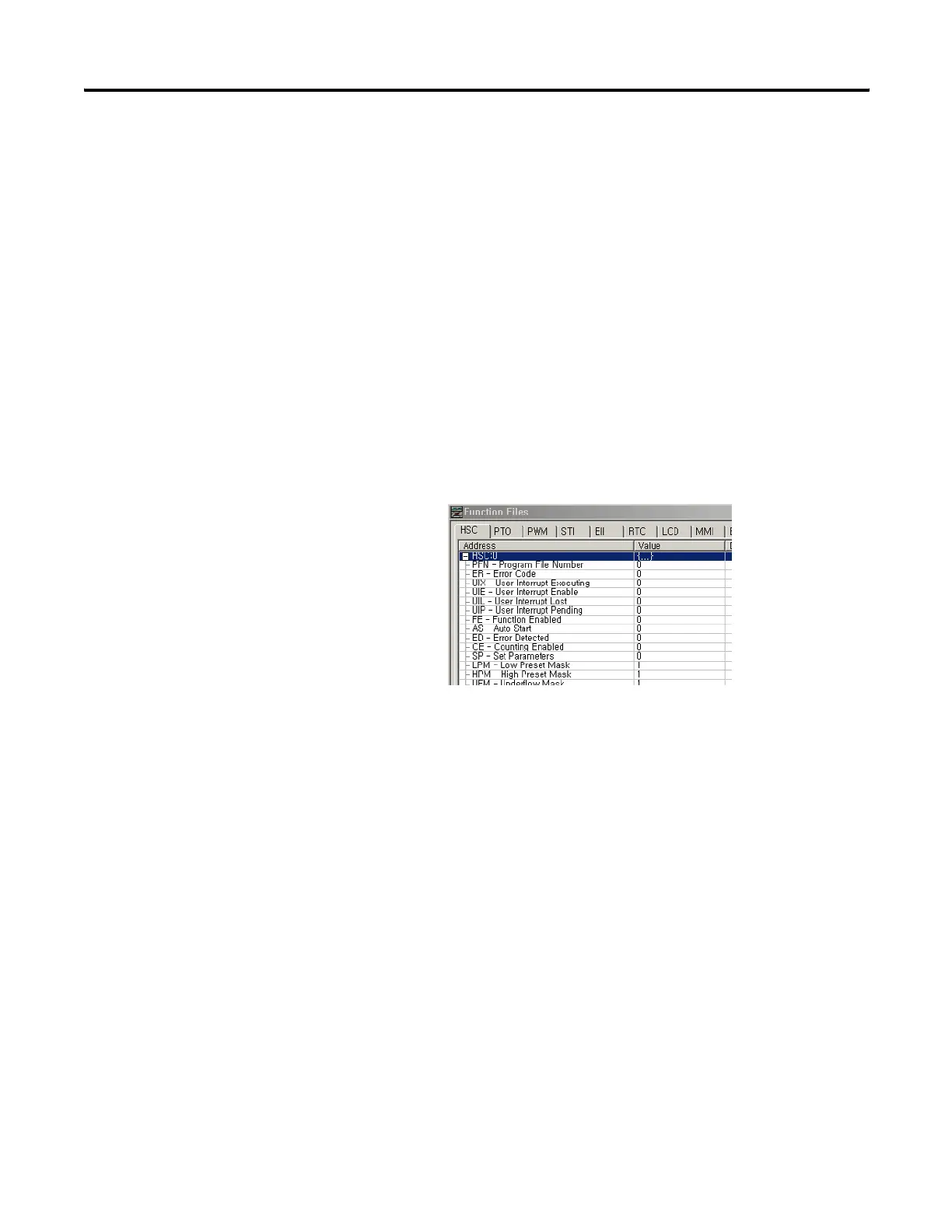
Locate the Function Files under Controller in RSLOGIX 500 and select the
HSC tab, then select the [+] next to HSC:0 (See Below)
Enter the following parameters for the “Minimum Configuration”
required for the HSC to count pulses.
Note: There is no additional ladder logic required to enable the High
Speed Counter. In other words there is no HSC instruction needed for the
ladder logic program.
HSC:0.PFN Program File Number defines which subroutine is executed when the HSC:0 accumulated
count equals the High or Low preset or passes through Overflow or Underflow. The
Integer number entered must be a valid sub-routine program file (3 to 255).
HSC:0/AS Auto-Start defines if the HSC function will automatically start when the MicroLogix enters
run or test.
HSC:0/CE Counting Enabled control bit is used to enable or disable the HSC
HSC:0.HIP High Preset is the upper set point (in counts) that defines when the HSC will generate an
interrupt and execute the PFN sub-routine.
efesotomasyon.com - Allen Bradley,Rockwell,plc,servo,drive

 Loading...


