EasyManuals Logo

Allen-Bradley MicroLogix 1100 Instruction Set Reference Manual

Allen-Bradley MicroLogix 1100
616 pages
To Next Page IconTo Next Page
To Previous Page IconTo Previous Page
Page #543 background imageLoading...
Page #543 background image
Publication 1763-RM001C-EN-P - October 2009
Knowledgebase Quick Starts 543
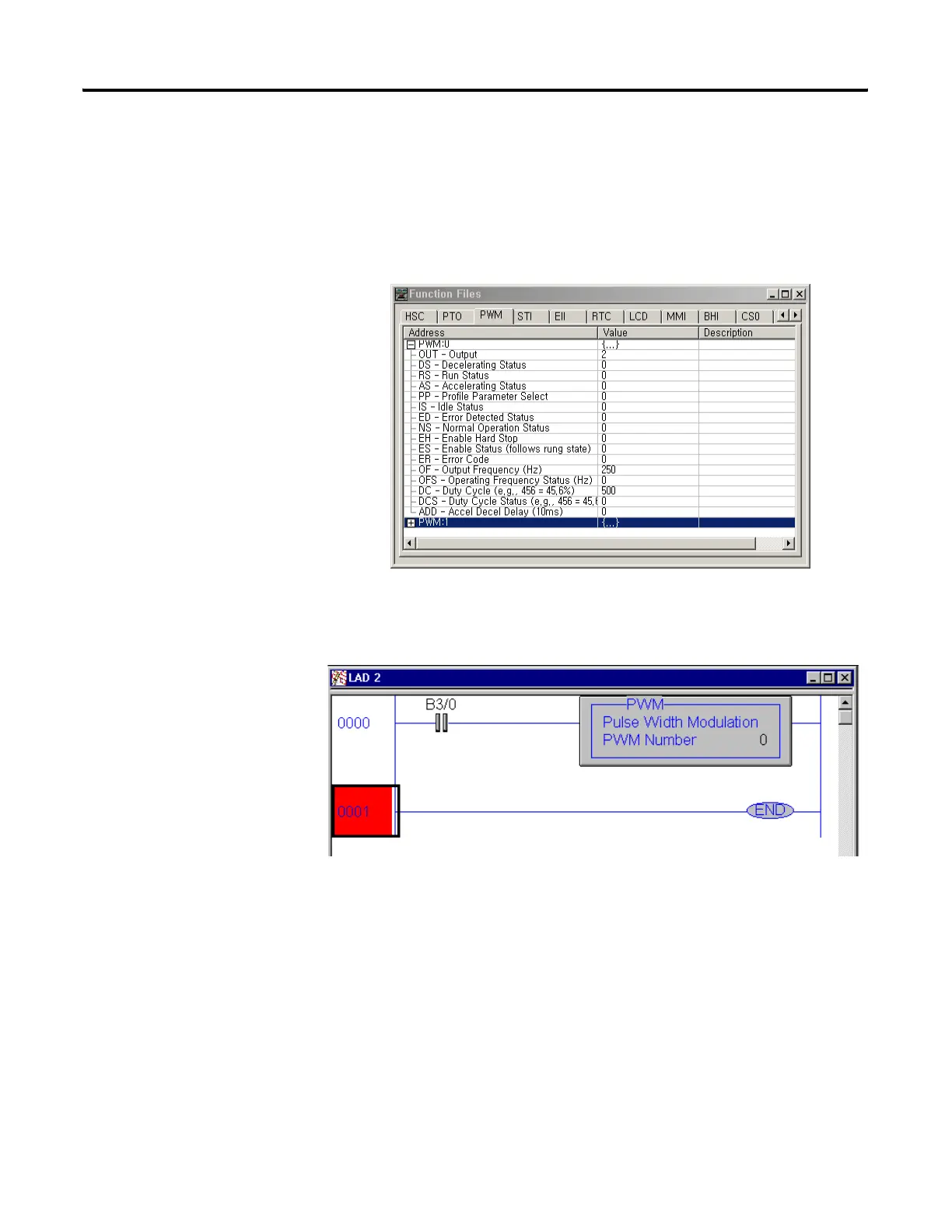
Example
The following example will generate a waveform on Output O:0/2 at a
frequency of 250Hz and a 50% Duty Cycle.
The following ladder logic will need to be entered into File #2
By toggling Bit B3/0 the PWM can be activated.
Note: Once activated the PWM will continue to generate a waveform until
B3/0 is toggled OFF or the PWM:0/EH (Enable Hard Stop) bit has been
activated.
efesotomasyon.com - Allen Bradley,Rockwell,plc,servo,drive

Table of Contents

Other manuals for Allen-Bradley MicroLogix 1100

Questions and Answers:

Question and Answer IconNeed help?

Do you have a question about the Allen-Bradley MicroLogix 1100 and is the answer not in the manual?

Allen-Bradley MicroLogix 1100 Specifications

General IconGeneral
Processor32-bit
Programming SoftwareRSLogix 500
MountingDIN rail or panel mount
Power Supply24V DC
TypeCompact PLC
Digital Inputs12
Digital Outputs8
Analog Inputs4 (depending on model)
Analog OutputsOptional with expansion module
Programming LanguageLadder Logic
Operating Temperature0 to 55 °C (32 to 131 °F)
SeriesMicroLogix

Related product manuals