Publication 1763-RM001C-EN-P - October 2009
120 Using the High-Speed Counter and Programmable Limit Switch
Programmable Limit
Switch (PLS) File
The Programmable Limit Switch function allows you to configure the
High-Speed Counter to operate as a PLS (programmable limit switch) or
rotary cam switch.
When PLS operation is enabled, the HSC (High-Speed Counter) uses a PLS
data file for limit/cam positions. Each limit/cam position has
corresponding data parameters that are used to set or clear physical
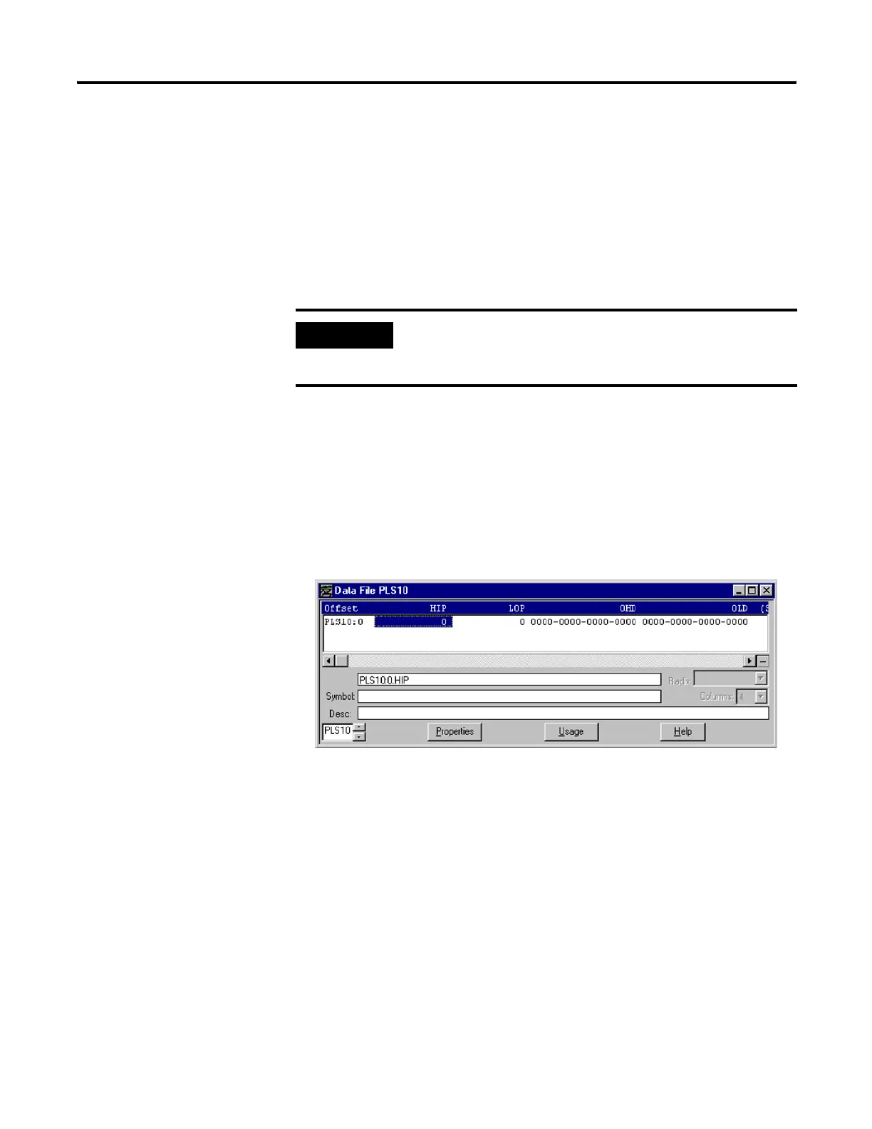
outputs on the controller’s base unit. The PLS data file is illustrated below.
PLS Data File
Data files 9 to 255 can be used for PLS operations. Each PLS data file can
be up to 256 elements long. Each element within a PLS file consumes 6
user words of memory. The PLS data file is shown below:
PLS Operation
When the PLS function is enabled, and the controller is in the run mode,
the HSC will count incoming pulses. When the count reaches the first
preset (High - HIP or Low - LOP) defined in the PLS file, the output
source data (High - OHD or Low - OLD) will be written through the HSC
mask.
At that point, the next preset (High - HIP or Low - LOP) defined in the PLS
file becomes active.
IMPORTANT
The PLS Function only operates in tandem with the HSC
of a MicroLogix 1100. To use the PLS function, an HSC
must first be configured.
efesotomasyon.com - Allen Bradley,Rockwell,plc,servo,drive

 Loading...


