EasyManuals Logo

Allen-Bradley MicroLogix 1100 Instruction Set Reference Manual

Allen-Bradley MicroLogix 1100
616 pages
To Next Page IconTo Next Page
To Previous Page IconTo Previous Page
Page #363 background imageLoading...
Page #363 background image
Publication 1763-RM001B-EN-P - April 2007
Communications Instructions 363
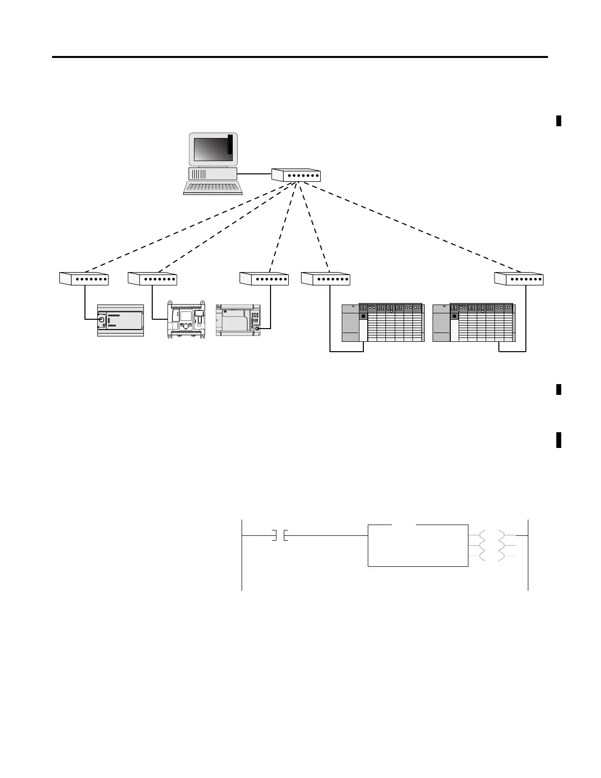
Example 3 - Local DF1 Half-Duplex Network
Configuring a Local
Message
Message Setup Screen
The rung below shows a MSG instruction preceded by conditional logic.
Access the message setup screen by double-clicking Setup Screen.
The RSLogix Message Setup Screen is shown below. This screen is used to
setup “This Controller”, “Target Device”, and “Control Bits”. Descriptions
of each of the elements follow.
RS-232
(DF1 Half-Duplex Protocol)
MicroLogix
1500 (Slave)
SLC 5/04 (Slave)
MicroLogix
1000 (Slave)
SLC 5/03 with 1747-KE
Interface Module (Slave)
MicroLogix
1100 (Slave)
Modem
0000
B3:0
0
EN
DN
ER
MSG
Read/Write Message
MSG File MG11:0
Setup Screen
MSG
efesotomasyon.com - Allen Bradley,Rockwell,plc,servo,drive

Table of Contents

Other manuals for Allen-Bradley MicroLogix 1100

Questions and Answers:

Question and Answer IconNeed help?

Do you have a question about the Allen-Bradley MicroLogix 1100 and is the answer not in the manual?

Allen-Bradley MicroLogix 1100 Specifications

General IconGeneral
Processor32-bit
Programming SoftwareRSLogix 500
MountingDIN rail or panel mount
Power Supply24V DC
TypeCompact PLC
Digital Inputs12
Digital Outputs8
Analog Inputs4 (depending on model)
Analog OutputsOptional with expansion module
Programming LanguageLadder Logic
Operating Temperature0 to 55 °C (32 to 131 °F)
SeriesMicroLogix

Related product manuals