EasyManuals Logo

Allen-Bradley MicroLogix 1100 Instruction Set Reference Manual

Allen-Bradley MicroLogix 1100
616 pages
To Next Page IconTo Next Page
To Previous Page IconTo Previous Page
Page #391 background imageLoading...
Page #391 background image
Publication 1763-RM001B-EN-P - April 2007
Communications Instructions 391
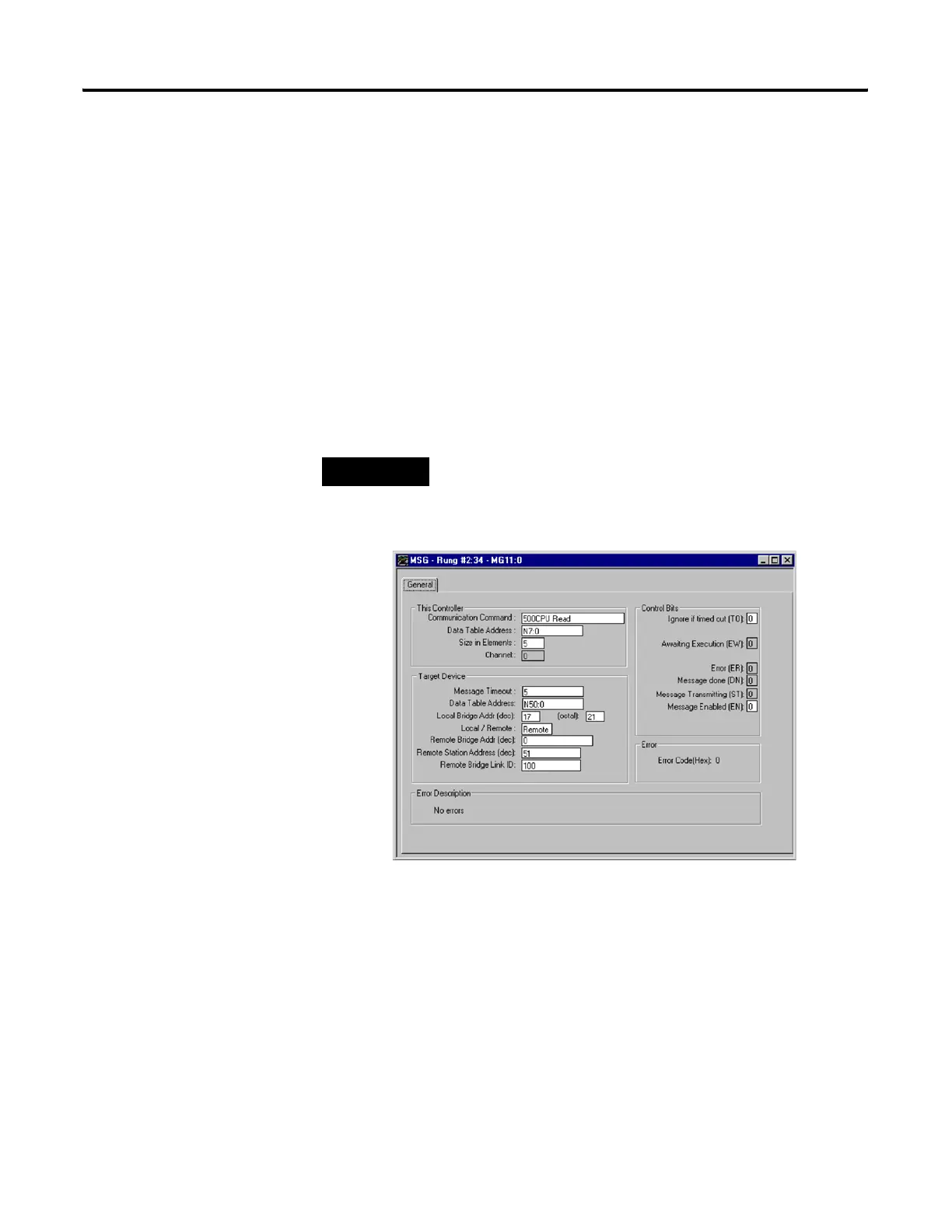
Configuring a Remote
Message
Remote capability is configured through the RSLogix 500 Message Setup
screen.
Example Configuration Screen and Network
The message configuration shown below is for the MicroLogix 1100 at
node 12 on the DH-485 network. This message reads five elements of
data from the SLC 5/04 (node 51 on the DH+ network) starting at address
N:50:0. The SLC 5/04 at Node 23 of the DH+ network is configured for
passthru operation.
TIP
The MicroLogix 1100 capabilities are the same as the
MicroLogix 1200 or MicroLogix 1500 in this example.
efesotomasyon.com - Allen Bradley,Rockwell,plc,servo,drive

Table of Contents

Other manuals for Allen-Bradley MicroLogix 1100

Questions and Answers:

Question and Answer IconNeed help?

Do you have a question about the Allen-Bradley MicroLogix 1100 and is the answer not in the manual?

Allen-Bradley MicroLogix 1100 Specifications

General IconGeneral
Processor32-bit
Programming SoftwareRSLogix 500
MountingDIN rail or panel mount
Power Supply24V DC
TypeCompact PLC
Digital Inputs12
Digital Outputs8
Analog Inputs4 (depending on model)
Analog OutputsOptional with expansion module
Programming LanguageLadder Logic
Operating Temperature0 to 55 °C (32 to 131 °F)
SeriesMicroLogix

Related product manuals