Publication 1763-RM001C-EN-P - October 2009
228 File Instructions
BSR - Bit Shift Right
Instruction Type: output
If you wish to shift more than one bit per scan, you must create a loop in
your application using the JMP, LBL, and CTU instructions.
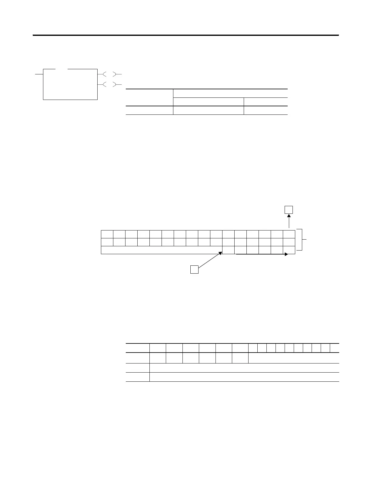
The BSR instruction loads data into a bit array on a false-to-true rung
transition, one bit at a time. The data is shifted right through the array,
then unloaded, one bit at a time. The following figure shows the
operation of the BSR instruction.
This instruction uses the following operands:
• File - The file operand is the address of the bit array that is to be
manipulated.
• Control - The control operand is the address of the BSR’s control
element. The control element consists of 3 words:
• Bit Address - The source is the address of the bit to be transferred
into the bit array at the last (highest) bit position.
EN
DN
BSR
Bit Shift Right
File #B3:3
Control R6:0
Bit Address I:0/15
Length 1<
BSR
Execution Time for the BSR Instruction
Controller When Rung Is:
True False
MicroLogix 1100 34.5 μs + 0.2 μs/word 34.5 μs
Data block is shifted one bit at
a time from bit 69 to bit 32.
Source Bit
I:23/06
38 Bit Array
#B3:2
Unload Bit
(R6:0/10)
47 46 45 44 43 42 41 40 39 38 37 36 35 34 33 32
63 62 61 60 59 58 57 56 55 54 53 52 51 50 49 48
INVALID 696867666564
15 14 13 12 11 10 9876543210
Word 0
EN
(1)
(1) EN - Enable Bit is set on false-to-true transition of the rung and indicates the instruction is enabled.
--
DN
(2)
(2) DN - Done Bit, when set, indicates that the bit array has shifted one position.
--
ER
(3)
(3) ER - Error Bit, when set, indicates that the instruction detected an error such as entering a negative number for the
length or source operand.
UL
(4)
(4) UL - Unload Bit is the instruction’s output. Avoid using the UL (unload) bit when the ER (error) bit is set.
not used
Word 1 Size of bit array (number of bits).
Word 2 not used
efesotomasyon.com - Allen Bradley,Rockwell,plc,servo,drive

 Loading...


