Publication 1763-RM001C-EN-P - October 2009
File Instructions 227
If you wish to shift more than one bit per scan, you must create a loop in
your application using the JMP, LBL, and CTU instructions.
This instruction uses the following operands:
• File - The file operand is the address of the bit array that is to be
manipulated.
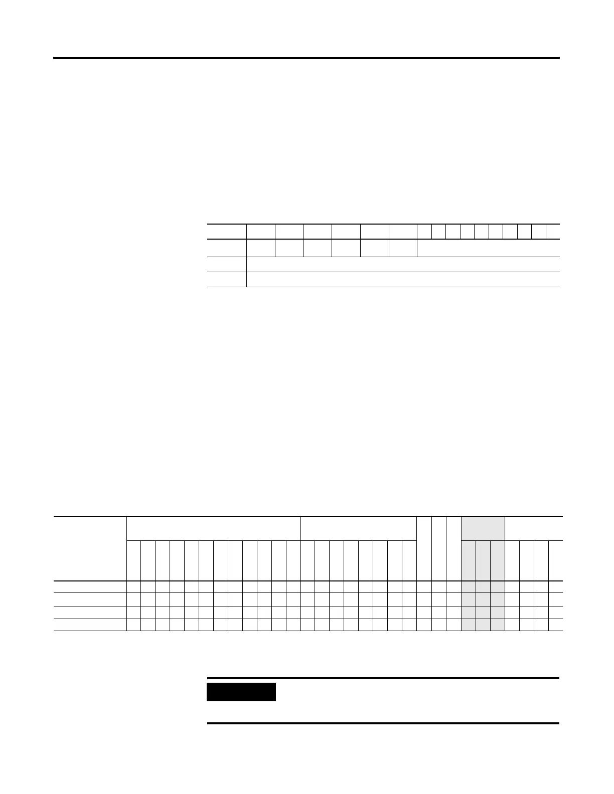
• Control - The control operand is the address of the BSL’s control
element. The control element consists of 3 words:
• Bit Address - The source is the address of the bit to be transferred
into the bit array at the first (lowest) bit position.
• Length - The length operand contains the length of the bit array in
bits. The valid data range for length is from 0 to 2048.
Addressing Modes and File Types can be used as shown in the following
table:
15 14 13 12 11 10 9876543210
Word 0
EN
(1)
(1) EN - Enable Bit is set on false-to-true transition of the rung and indicates the instruction is enabled.
--
DN
(2)
(2) DN - Done Bit, when set, indicates that the bit array has shifted one position.
--
ER
(3)
(3) ER - Error Bit, when set, indicates that the instruction detected an error such as entering a negative number for the
length or source operand.
UL
(4)
(4) UL - Unload Bit is the instruction’s output. Avoid using the UL (unload) bit when the ER (error) bit is set.
not used
Word 1 Size of bit array (number of bits).
Word 2 not used
BSL Instruction Valid Addressing Modes and File Types
For definitions of the terms used in this table see Using the Instruction Descriptions on page 82.
Parameter
Data Files Function Files
CS - Comms
IOS - I/O
DLS - Data Log
Address
Mode
(1)
Address Level
O
I
S
B
T, C, R
N
F
ST
L
MG, PD
RI/RIX
PLS
RTC
HSC
PTO, PWM
STI
EII
BHI
MMI
LCD
Immediate
Direct
Indirect
Bit
Word
Long Word
Element
File •••• •• • •••
Control
(2)
• •
Length
• •
Source •• ••• •
• ••
(1) See Important note about indirect addressing.
(2) Control file only. Not valid for Timers and Counters.
IMPORTANT
You cannot use indirect addressing with: S, ST, MG, PD,
RTC, HSC, PTO, PWM, STI, EII, BHI, MMI, CS, IOS, and
DLS files.
efesotomasyon.com - Allen Bradley,Rockwell,plc,servo,drive

 Loading...


