Publication 1763-RM001C-EN-P - October 2009
174 Timer and Counter Instructions
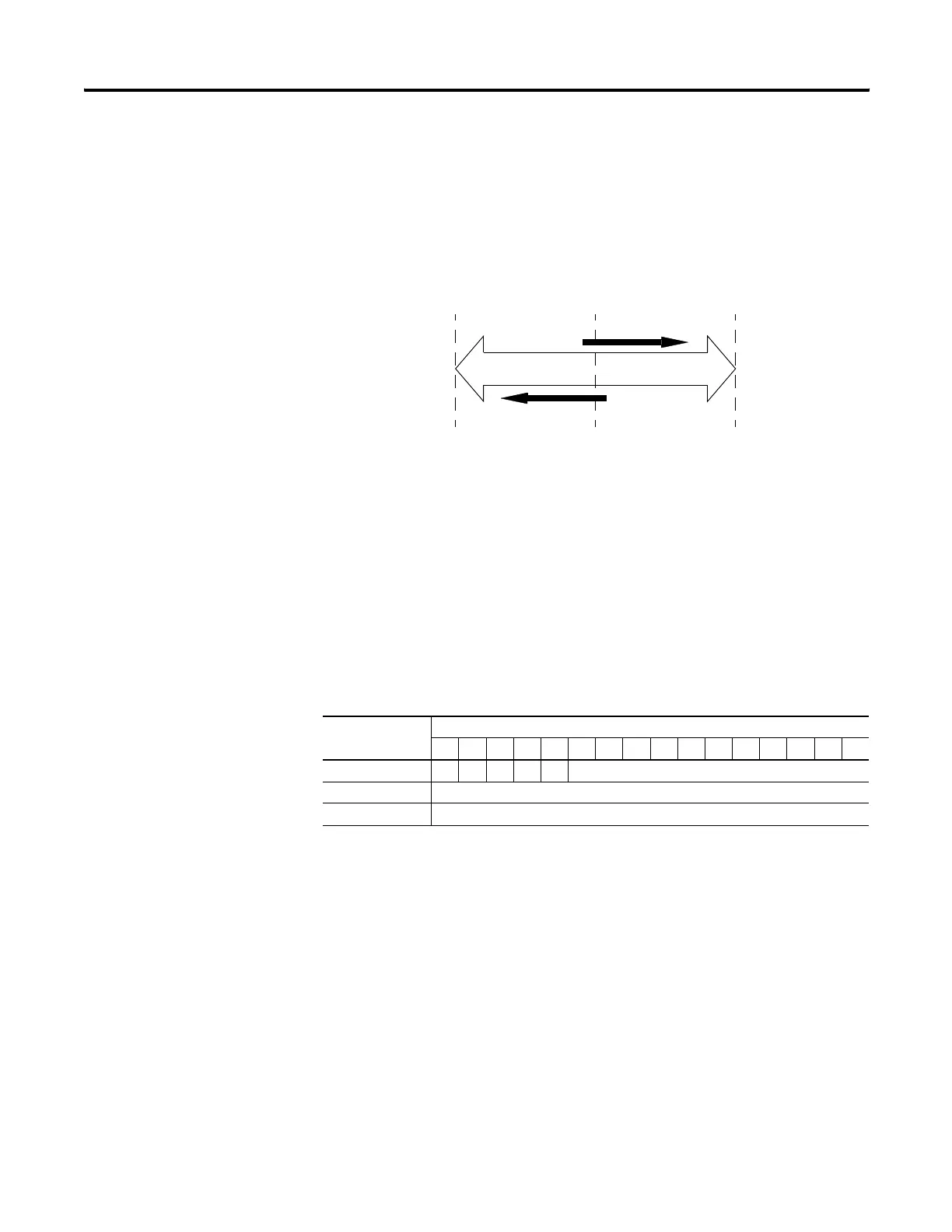
How Counters Work
The figure below demonstrates how a counter works. The count value
must remain in the range of -32,768 to +32,767. If the count value goes
above +32,767, the counter status overflow bit (OV) is set (1). If the count
goes below -32,768, the counter status underflow bit (UN) is set (1). A
reset (RES) instruction is used to reset (0) the counter.
Using the CTU and CTD Instructions
Counter instructions use the following parameters:
• Counter - This is the address of the counter within the data file. All
counters are 3-word data elements. Word 0 contains the Control and
Status Bits, Word 1 contains the Preset, and Word 2 contains the
Accumulated Value.
CU = Count Up Enable Bit
CD = Count Down Enable Bit
DN = Count Done Bit
OV = Count Overflow Bit
UN = Count Underflow Bit
• Preset - When the accumulator reaches this value, the DN bit is set.
The preset data range is from -32768 to 32767.
• Accumulator - The accumulator contains the current count. The
accumulator data range is from -32768 to 32767.
The accumulated value is incremented (CTU) or decremented (CTD)
on each false-to-true rung transition. The accumulated value is
retained when the rung condition again becomes false, and when
power is cycled on the controller. The accumulated count is
Word Bit
1514131211109876543210
Word 0 CUCDDNOVUNNot Used
Word 1 Preset Value
Word 2 Accumulated Value
-32,768 +32,7670
OverflowUnderflow
Counter Accumulator Value
Count Up
Count Down
efesotomasyon.com - Allen Bradley,Rockwell,plc,servo,drive

 Loading...


