Publication 1763-RM001C-EN-P - October 2009
Timer and Counter Instructions 175
retained until cleared by a reset (RES) instruction that has the same
address as the counter.
Addressing Modes and File Types can be used as shown in the following
table:
Using Counter File Control and Status Bits
Like the accumulated value, the counter status bits are also retentive until
reset, as described below.
TIP
The counter continues to count when the accumulator is
greater than the CTU preset and when the accumulator is
less than the CTD preset.
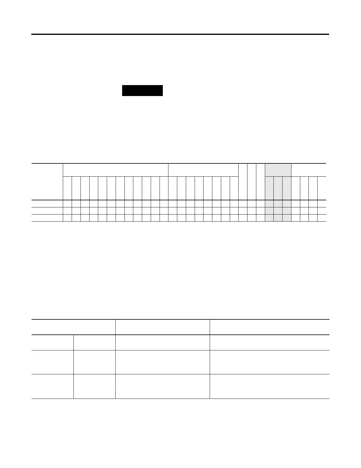
CTD and CTU Instructions Valid Addressing Modes and File Types
For definitions of the terms used in this table see Using the Instruction Descriptions on page 82.
Parameter
Data Files
(1)
Function Files
CS - Comms
IOS - I/O
DLS - Data Log
Address
Mode
Address Level
O
I
S
B
T, C, R
N
F
ST
L
MG, PD
RI/RIX
PLS
RTC
HSC
PTO, PWM
STI
EII
BHI
MMI
LCD
Immediate
Direct
Indirect
Bit
Word
Long Word
Element
Counter • • •
Preset
• •
Accumulator
• •
(1) Valid for Counter Files only.
CTU Instruction Counter Control and Status Bits, Counter Word 0
(Data File 5 is configured as a timer file for this example.)
Bit Is Set When: And Remains Set Until One of the Following
Occurs:
bit 12 - C5:0/OV OV - overflow
indicator
the accumulated value wraps from +32,767
to -32,768 and continues to count up
a RES instruction with the same address as the CTU
instruction is enabled
bit 13 - C5:0/DN DN - done
indicator
accumulated value
≥ preset value •accumulated value < preset value or,
•a RES instruction with the same address as the CTU
instruction is enabled
bit 15 - C5:0/CU CU - count up
enable
rung state is true •rung state is false
•a RES instruction with the same address as the CTU
instruction is enabled
efesotomasyon.com - Allen Bradley,Rockwell,plc,servo,drive

 Loading...


