Publication 1763-RM001C-EN-P - October 2009
Using the High-Speed Counter and Programmable Limit Switch 121
When the HSC counts to that new preset, the new output data is written
through the HSC mask. This process continues until the last element
within the PLS file is loaded. At that point the active element within the
PLS file is reset to zero. This behavior is referred to as circular operation.
If invalid data is loaded during operation, an HSC error is generated
(within the HSC function file). The error will not cause a controller fault. If
an invalid parameter is detected, it will be skipped and the next
parameter will be loaded for execution (provided it is valid).
You can use the PLS in Up (high), Down (low), or both directions. If your
application only counts in one direction, simply ignore the other
parameters.
The PLS function can operate with all of the other HSC capabilities. The
ability to select which HSC events generate a user interrupt are not
limited.
Addressing PLS Files
The addressing format for the PLS file is shown below.
TIP
The Output High Data (OHD) is only written when the
High preset (HIP) is reached. The Output Low Data
(OLD) is written when the low preset is reached.
TIP
Output High Data is only operational when the counter
is counting up. Output Low Data is only operational
when the counter is counting down.
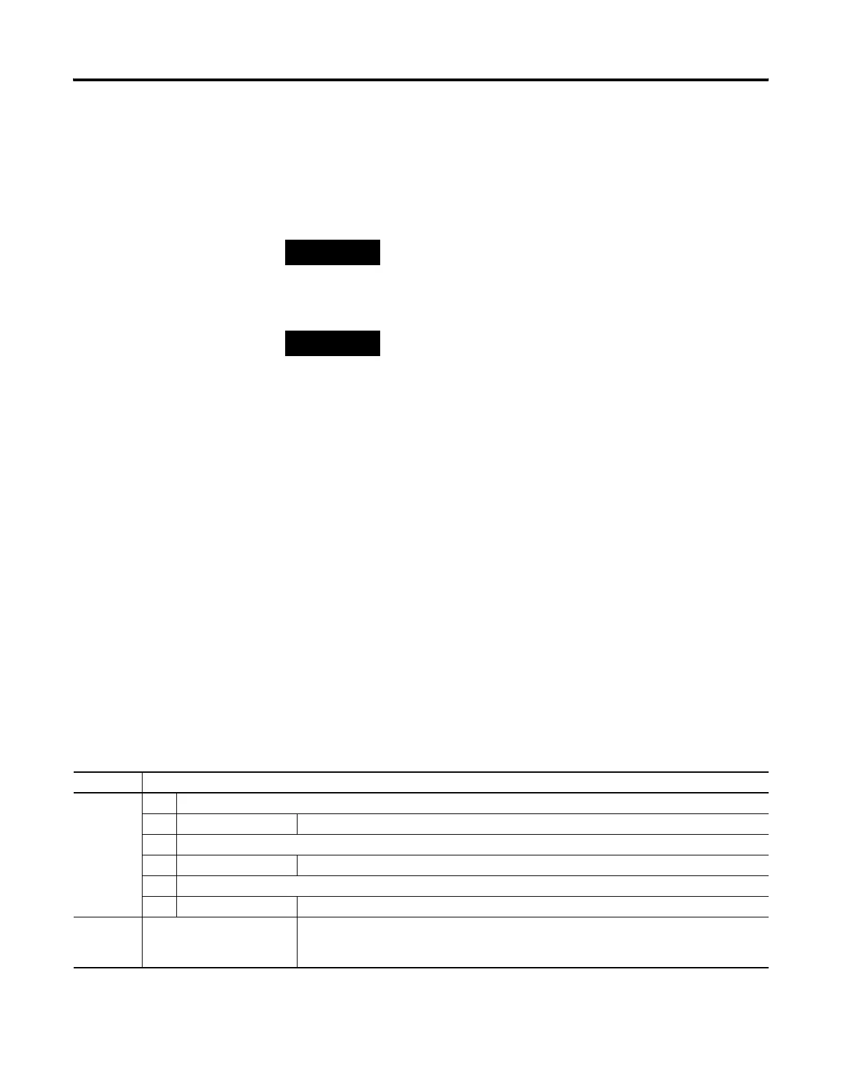
Format Explanation
PLSf:e.s PLS Programmable Limit Switch file
f File number The valid file number range is from 9 to 255.
: Element delimiter
e Element number The valid element number range is from 0 to 255.
. Sub-Element delimiter
s Sub-Element number The valid sub-element number range is from 0 to 5
Examples: PLS10:2
PLS12:36.5
PLS File 10, Element 2
PLS File 12, Element 36, Sub-Element 5 (Output Low Source)
efesotomasyon.com - Allen Bradley,Rockwell,plc,servo,drive
 Loading...


