Publication 1763-RM001C-EN-P - October 2009
Using the High-Speed Counter and Programmable Limit Switch 125
PLS Data File Definitions:
Once the values above have been entered for HIP and OHD, the
PLS is configured.
Configuring the HSC for Use with the PLS
1. Under Controller, double-click on Function Files.
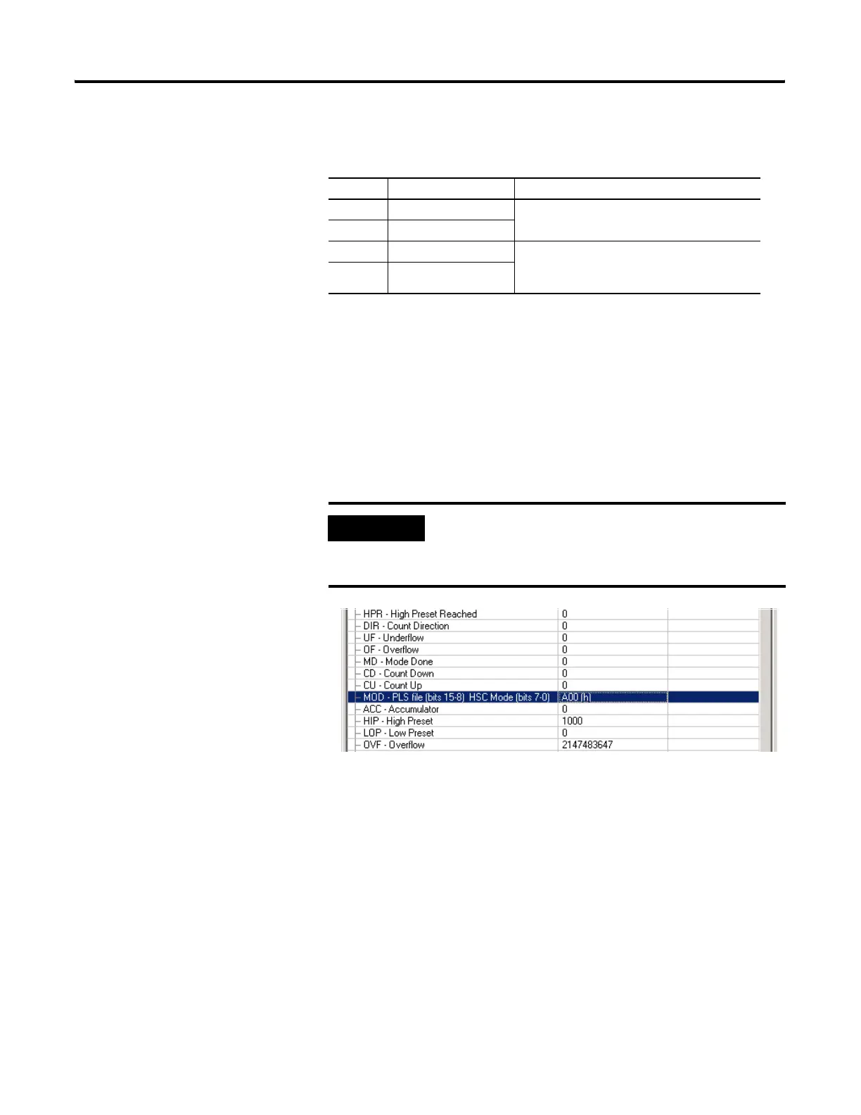
2. For HSC:0, configure the HSC.MOD to use PLS10 and for the HSC to
operate in mode 00.
PLS Operation for This Example
When the ladder logic first runs, HSC.ACC equals 0, therefore
PLS10:0.OLD's data is sent through the HSC.OMB mask and sets all the
outputs off.
When HSC.ACC equals 250, the PLS10:0.OHD is sent through the
HSC.OMB mask and energizes the outputs.
This will repeat as the HSC.ACC reaches 500, 750, and 1000. Once
completed, the cycle resets and repeats.
Data Description Data Format
HIP High Preset 32-bit signed integer
LOP Low Preset
OHD Output High Data 16-bit binary
(bit 15--> 0000 0000 0000 0000 <--bit 0)
OLD Output Low Data
IMPORTANT
The value for MOD must be entered in
Hexadecimal.
For example, PLS10 = 0A and HSC Mode = 00
efesotomasyon.com - Allen Bradley,Rockwell,plc,servo,drive

 Loading...


