Publication 1763-RM001C-EN-P - October 2009
154 Using High-Speed Outputs
• Set (1) - Whenever a PWM output is within the acceleration phase of
the output profile.
• Cleared (0) - Whenever a PWM output is not within the acceleration
phase of the output profile.
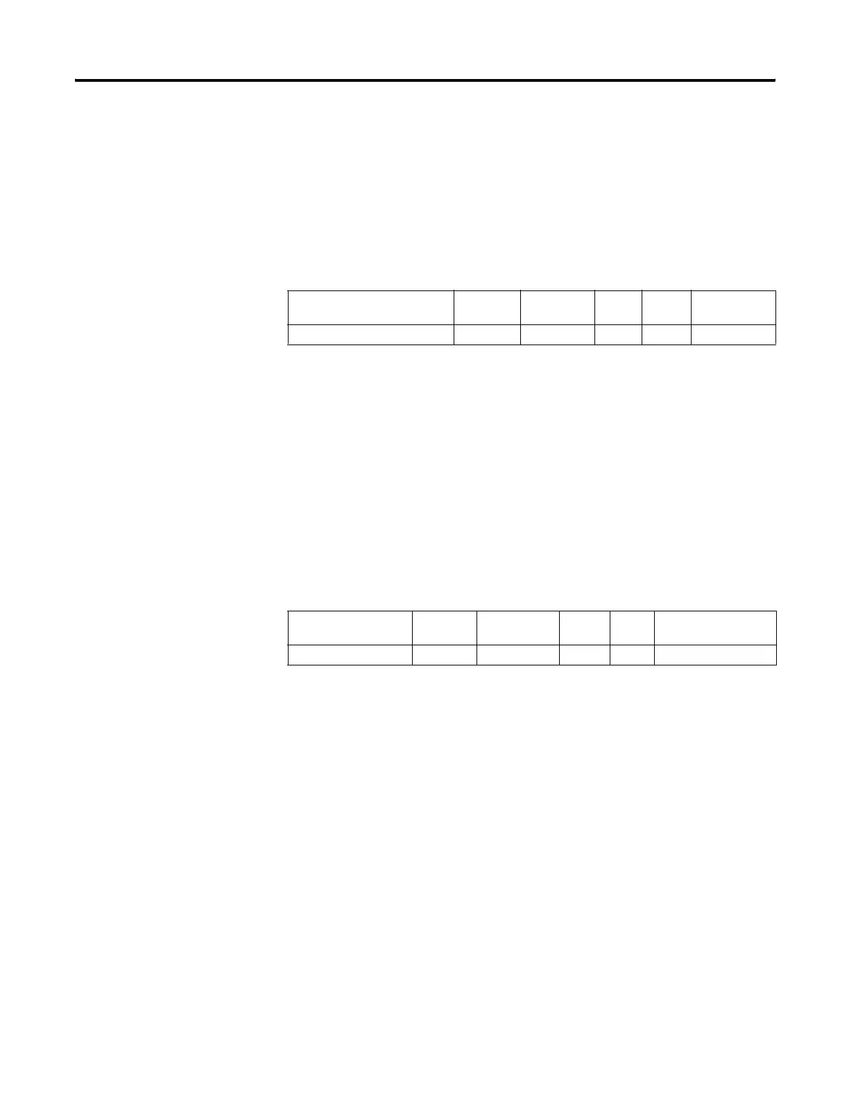
PWM Profile Parameter Select (PP)
The PWM PP (Profile Parameter Select) selects which component of the
waveform is modified during a ramp phase:
• Set (1) - selects Frequency
• Cleared (0) - selects Duty Cycle
The PWM PP bit cannot be modified while the PWM output is running/
enabled. See PWM ADD on page 158 for more information.
PWM Idle Status (IS)
The PWM IS (Idle Status) is controlled by the PWM sub-system and
represents no PWM activity. It can be used in the control program by an
input instruction.
• Set (1) - PWM sub-system is in an idle state.
• Cleared (0) - PWM sub-system is not in an idle state (it is running).
Element Description Address Data Format Range Type User Program
Access
PP - Profile Parameter Select PWM:0/PP bit 0 or 1 control read/write
Element Description Address Data Format Range Type User Program
Access
IS - PWM Idle Status PWM:0/IS bit 0 or 1 status read only
efesotomasyon.com - Allen Bradley,Rockwell,plc,servo,drive

 Loading...


