Publication 1763-RM001C-EN-P - October 2009
160 Relay-Type (Bit) Instructions
When used on a rung, the bit address being examined can correspond to
the status of real world input devices connected to the base unit or
expansion I/O, or internal addresses (data or function files). Examples of
devices that turn on or off:
• a push button wired to an input (addressed as I1:0/4)
• an output wired to a pilot light (addressed as O0:0/2)
• a timer controlling a light (addressed as T4:3/DN)
• a bit in the bit file (addressed as B3/16)
The instructions operate as follows:
Addressing Modes and File Types can be used as shown in the following
table:
XIO and XIC Instruction Operation
Rung State Addressed
Bit
XIC Instruction XIO Instruction
True Off Returns a False Returns a True
True On Returns a True Returns a False
False -- Instruction is not evaluated Instruction is not evaluated
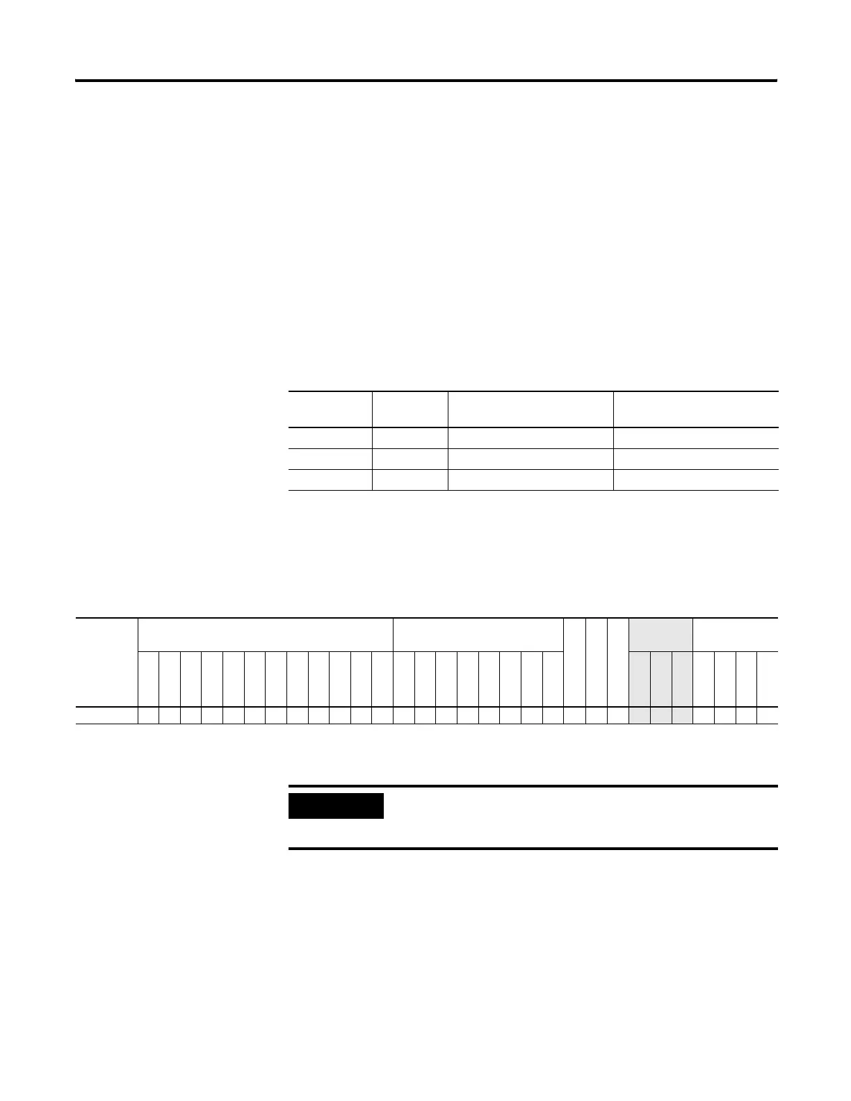
XIC and XIO Instructions Valid Addressing Modes and File Types
For definitions of the terms used in this table see Using the Instruction Descriptions on page 82.
Parameter
Data Files
Function Files
(1)
CS - Comms
IOS - I/O
DLS - Data Log
Address
Mode
(2)
Address Level
O
I
S
B
T, C, R
N
F
ST
L
MG, PD
RI/RIX
PLS
RTC
HSC
PTO, PWM
STI
EII
BHI
MMI
LCD
Immediate
Direct
Indirect
Bit
Word
Long Word
Element
Operand Bit •••••• •• ••••••••••• • ••
(1) PTO and PWM files are only for use with MicroLogix 1100 BBB unit.
(2) See Important note about indirect addressing.
IMPORTANT
You cannot use indirect addressing with: S, ST, MG, PD,
RTC, HSC, PTO, PWM, STI, EII, BHI, MMI, CS, IOS, LCD,
and DLS files.
efesotomasyon.com - Allen Bradley,Rockwell,plc,servo,drive

 Loading...


