Publication 1763-RM001C-EN-P - October 2009
168 Timer and Counter Instructions
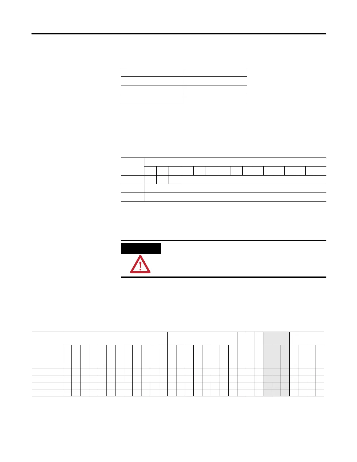
Each timer address is made of a 3-word element. Word 0 is the control
and status word, word 1 stores the preset value, and word 2 stores the
accumulated value.
EN = Timer Enable Bit
TT = Timer Timing Bit
DN = Timer Done Bit
Addressing Modes and File Types can be used as shown in the following
table:
Timer Base Settings
Time Base Timing Range
0.001 seconds 0 to 32.767 seconds
0.01 seconds 0 to 327.67 seconds
1.00 seconds 0 to 32,767 seconds
Timer File
Word Bit
1514131211109 8 76543210
Word 0 EN TT DN Internal Use
Word 1 Preset Value
Word 2 Accumulated Value
ATTENTION
Do not copy timer elements while the timer enable bit
(EN) is set. Unpredictable machine operation may occur.
Timer Instructions Valid Addressing Modes and File Types
For definitions of the terms used in this table see Using the Instruction Descriptions on page 82.
Parameter
Data Files
(1)
Function Files
CS - Comms
IOS - I/O
DLS - Data Log
Address
Mode
Address Level
O
I
S
B
T, C, R
N
F
ST
L
MG, PD
RI/RIX
PLS
RTC
HSC
PTO, PWM
STI
EII
BHI
MMI
LCD
Immediate
Direct
Indirect
Bit
Word
Long Word
Element
Timer • • •
Time Base
• •
Preset
• •
Accumulator
• •
(1) Valid for Timer Files only.
efesotomasyon.com - Allen Bradley,Rockwell,plc,servo,drive

 Loading...


