Publication 1763-RM001C-EN-P - October 2009
File Instructions 235
• Control - This is a control file address. The status bits, stack length,
and the position value are stored in this element. The control
element consists of 3 words:
• Length - The length operand contains the number of elements in the
FIFO stack to receive the value or constant found in the source. The
length of the stack can range from 1 to 128 (word) or 1 to 64 (long
word). The position is incremented after each load.
• Position - This is the current location pointed to in the LIFO stack. It
determines the next location in the stack to receive the value or
constant found in source. Position is a component of the control
register. The position can range from 0 to 127 (word) or 0 to 63
(long word).
Addressing Modes and File Types can be used as shown in the following
table:
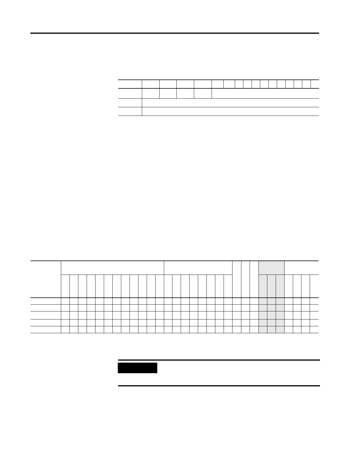
15 14 13 12 11 10 9 8 7 6 5 4 3 2 1 0
Word 0
EN
(1)
(1) EN - Enable Bit is set on false-to-true transition of the rung and indicates the instruction is enabled.
--
DN
(2)
(2) DN - Done Bit, when set, indicates that the stack is full.
EM
(3)
(3) EM - Empty Bit, when set, indicates that LIFO is empty.
not used
Word 1 Length - maximum number of words or long words in the stack.
Word 2 Position - the next available location where the instruction loads data.
LFL Instruction Valid Addressing Modes and File Types
For definitions of the terms used in this table see Using the Instruction Descriptions on page 82.
Parameter
Data Files Function Files
CS - Comms
IOS - I/O
DLS - Data Log
Address
Mode
(1)
Address Level
O
I
S
B
T, C, R
N
F
ST
L
MG, PD
RI/RIX
PLS
RTC
HSC
PTO, PWM
STI
EII
BHI
MMI
LCD
Immediate
Direct
Indirect
Bit
Word
Long Word
Element
Source •• ••• • • • • •••
LIFO • • • • • •
• •••
Control
(2)
• •
Length
• •
Position
• •
(1) See Important note about indirect addressing.
(2) Control file only. Not valid for Timers and Counters.
IMPORTANT
You cannot use indirect addressing with: S, ST, MG, PD,
RTC, HSC, PTO, PWM, STI, EII, BHI, MMI, CS, IOS, and
DLS files.
efesotomasyon.com - Allen Bradley,Rockwell,plc,servo,drive

 Loading...


